
Install Instructions


17
FUEL PIPING
A. INSTALLATION
1. Pipe gas to the boiler in accordance with local codes.
In the absence of local regulations refer to the
National Fuel Gas Code, ANSI Z223.1/NFPA 54.
2. Size and install the gas supply piping to provide a
supply of gas sufficient to meet the maximum demand
of all appliances without excessive pressure drop.
3. The rate of gas to be provided to the boiler can be
determined by:
Obtain the gas heating value of the gas from the gas
supplier. As an alternative use Table 5.1.
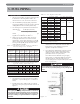
4. Table 5.2 shows the maximum flow capacity of
several pipe sizes based on 0.3 inches of water
pressure drop. These values are based on a specific
gravity of 0.60. Apply the factors indicated in Table
5.3 for gas with specific gravity other than 0.60 to
obtain corrected capacities.
B. OPERATION
1. Assure that the gas supply pressure to the boiler is
regulated to 1/2 psi or less (approx. 13.5 inches of
water).
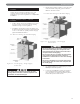
2. Install a service valve, sediment trap, and ground
joint union at the gas supply connection as shown in
Figure 5.1.
3. Check piping for leaks. Use an approved gas
detector or a non-corrosive leak detection fluid. If
leaks are found, turn off all gas supply to the
appliance and repair as necessary.
4. The boiler and its individual shut off valve must be
disconnected from the gas supply piping system
during any pressure testing of that system at test
pressures in excess of 1/2 psi (3.5kPa).
The boiler must be isolated from the gas supply
piping system by closing its individual manual shut
off valve during any pressure testing of the gas
supply piping system at test pressures equal to or less
than 1/2 psi (3.5 kPa).
5. FUEL PIPING
Based on Specific Gravity of 0.60
Pipe Length
(Feet)
1/2"
Pipe
3/4"
Pipe
1"
Pipe
1-1/4"
Pipe
1-1/2"
Pipe
10 132 278 520 1,050 1,600
20 92 190 350 730 1,100
30 73 152 285 590 890
40 63 130 245 500 760
50 56 115 215 440 670
60 50 105 195 400 610
Table 5.2: Maximum Capacity of Pipe in CFH for a
Pressure Drop of 0.3" of Water
Table 5.3: Maximum Capacity Correction Factors
Specific Gravity other than 0.60
Table 5.1: Gas Input & Valve Inlet
Do not subject the boiler gas valve to pressure in
excess of 1/2 psi (3.5 kPa). Doing so may damage the
valve.
CAUTION
Figure 5.1
Specific Gravity 0.50 0.55 0.60 0.65 0.70 0.75
Correction Factor 1.10 1.04 1.00 0.96 0.93 0.90
Specific Gravity 0.80 0.85 0.90 1.00 1.10 1.20
Correction Factor 0.87 0.84 0.82 0.78 0.74 0.71
Specific Gravity 1.30 1.40 1.50 1.60 1.70 1.80
Correction Factor 0.68 0.66 0.63 0.61 0.59 0.58
Use a pipe joint sealing compound that is resistant to
the action of liquefied petroleum gas. A non-resistant
compound may lose sealing ability in the presence of
this gas, resulting in a gas leak and fire or explosion
potential.
CAUTION
Boiler Input (BTU/HR)
CFH =
Gas Heating Value (BTU/FT³)
Model
Gas Input
1
(CFH) Gas Valve Inlet
2
(NPT)
Nat. Gas LP Gas Nat. Gat LP Gas
63-03L 88.5 35.4
1/2" 1/2"
63-03 118.0 47.2
63-04L 147.5 59.0
63-04 177.0 70.8
63-05L 206.5 82.6
3/4"
3/4"
63-05 236.0 94.4
63-06 287.5 115.0
64-07 345.0 138.0
64-08 399.0 159.6
64-09 460.0 184.0
1"
64-10 517.5 207.0
64-11 575.0 230.0
64-12 632.5 253.0
1. Natural Gas Based on 1000 Btu./Cubic Foot, LP Gas Based on 2500 Btu./Cubic Foot.
2. See instructions for sizing gas supply piping.