
User Manual


Basic Operation
WARNING
Service on this boiler should be undertaken only by trained and skilled personnel from a
qualified service agency.
2
CAUTION
Should overheating occur or the gas supply fail to shut off, do not turn off or disconnect the
electrical supply to the pump. Instead, shut off the gas supply at a location external to the
appliance.
Do not use this boiler if any part has been under water. Immediately call a qualified service
agency to inspect the boiler and to replace any part of the control system and any gas control
which has been under water.
A. General. This water boiler is a natural draft appliance and is equipped with controls for proper
operation. All controls must be in proper working order. Contact a qualified service agency to provide
annual maintenance as specified in the Installation, Operation and Maintenance Manual.
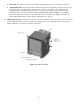
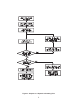
B. Control Locations. See Figure 1 for Control and Safety Device Locations.
1a. Limit (Steam Boiler). An electrical device that automatically interrupts the boiler operation when
the steam pressure exceeds the “CUT IN” pressure plus the differential (1 to 5 psi). Maximum
Pressure setting is 14 psig. The set point is usually less than 5 psig.
Original equipment with this boiler is a Honeywell PA404A1009. Boiler operation is interrupted
when the steam pressure exceeds the the “CUT IN” pressure plus the differential. Boiler operation
resumes automatically when the system pressure falls below the “CUT IN” pressure.
1b. Limit (Water Boiler). An electrical device that automatically interrupts the boiler operation when
the water temperature exceeds the set point. Maximum temperature setting is 220°F.
Original equipment with this boiler is a Honeywell L4080B1253. Boiler operation is interrupted
when the water temperature exceeds the set point. Boiler operation resumes automatically when
the water temperature falls to approximately 15°F below the set point.
2. Flame Rollout Switch (FRS). An electrical device that automatically interrupts the boiler operation
when excessive heat is present in the combustion area. The control is a thermal fuse device that
will require replacement if it is activated. If the control has been activated to interrupt the boiler
operation, do not attempt to restart the boiler. Contact a qualified service agency.
3. Blocked Vent Switch (BVS) An electrical device that automatically interrupts the boiler operation
when there is a blockage in the vent pipe or chimney. The control is located on the side of the draft
hood and is a manual reset device. If the control is activated to interrupt operation of the boiler, do
not attempt to restart the boiler. Contact a qualified service agency.
4. Pilot. The pilot provides an ignition source for the main burners. Your boiler has either a standing
(continuous) pilot or an intermittent (spark ignited) pilot. The standing pilot should always be lit
while the intermittent pilot ignites only when there is a call for heat and extinguishes when the call
for heat ends. See Figure 8.