
User Guide


c. Remove burners and brush gas outlet ports
lightly using a soft bristle brush. If there is
extensive corrosion in outlet ports, replace
burners.
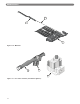
d. Remove the vent pipe, vent damper, top jacket
panel, flue collector/draft diverter, and flue
baffles.
e. Brush flueways with wire brush.
f. To the extent possible, inspect inside of vent
pipe and vent damper for obstructions in flow or
vent damper movement. Remove or replace as
necessary.
g. Re-install flue baffles. When replacing the flue
collector/draft hood, be certain that the blanket
seal between the flue collector and top section
makes a tight seal to prevent leakage of the
products of combustion.
h. Re-install the top of the jacket, vent damper and
vent pipe.
i. Re-install burners.
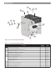
2. Inspect entire vent system for signs of deterioration,
corrosion, continuous wetness, inadequate support,
and joint integrity.
Inadequate vent configuration and low boiler
water temperatures contribute to the formation of
condensate, which will deteriorate the vent system.
If operating at low system water temperatures, such
as radiant systems or high mass radiation, a bypass
must be installed.
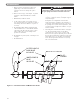
3. Check the pilot and main burner flame. See Figure
9.1. The pilot should provide a steady flame
enveloping 3/8″ to 1/2″ (1 cm to 1.2 cm) of the
flame sensor. If required, adjust the pilot as stated in
the gas valve manufacturer’s instructions. The main
burner flame inner cone should be approximately
1-1/2″ (4 cm) high and should have a very sharp,
blue color characteristic.
MAINTENANCE
OUTER CONE IS
DARK BLUE
IN COLOR
INNER CONE IS
BLUE
IN COLOR
PILOT
FLAMES
Figure 9.1: Intermittent Pilot and Main Burner Flame
WARNING
A deteriorated or incorrect vent system can result in
flue gas spillage and carbon monoxide emissions.
30