
User Guide


8
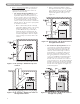
A. BOILER SUPPLY & RETURN
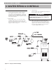
1. Size the supply and return to suit the system. A
typical piping arrangement is shown in Figure
3.1. Refer also to the I=B=R Guide - Residential
Hydronic Heating Installation/Design and the PB
Heat Water Survey for additional guidance during
water piping installation.
2. Return Piping:
Pipe the drain valve to a tee, provided, and the
1-1/4 NPT return tapping near the bottom of the
left section. Pipe the return to the tee. Pipe the
drain valve nipples and tee to the 1-1/4 NPT return
tapping as shown in Figure 3.1.
3. Supply Piping:
Pipe the supply to the 1-1/2 NPT supply tapping at
the top and rear of the boiler.
4. When system return water temperature will be
below 130°F (54°C), pipe the boiler with a bypass
arrangement to blend the system return and hot
supply to obtain at least 130°F (54°C) entering the
boiler. For more information on bypass piping,
consult the PB Heat Water Survey.
3. WATER PIPING & CONTROLS
Figure 3.1: Supply and Return Piping
WATER PIPING & CONTROLS
Low water temperatures can deteriorate the vent
system, which can result in flue gas spillage and
carbon monoxide emissions.
WARNING