
HydroStat User Guide


3
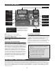
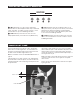
WIRING
WARNING
Electrical shock hazard. To prevent electrical shock, death or equipment damage, disconnect power supply before
installing or servicing this control.
All wiring must comply with the National Electric Code or any other state or local codes or
regulations.
Temp/Water
Sensor
DHW or Zone 2
Line Voltage
Plug
Inducer Plug
(inducer model only)
Vent Damper Plug
(atmospheric model only)
1
3
4
6
7
9
2
5
8
1
2
3
4
5
6
1
2
3
4
5
6
1
2
3
4
5
1
2
1
2
INDUCER
INDUCER
MOTOR
(INDUCER
MODEL ONLY)
HEATING
CIRCULATOR
DHW
CIRCULATOR
GND
GND
GND
GND
GND
DHW
VENT
DAMPER
VENT DAMPER
(ATMOSPHERIC MODEL ONLY)
AIR PRESSURE SWITCH
(INDUCER MODEL ONLY)
LIMITS
DHW
THERMOSTAT
LINE
VOLTAGE
LOW
VOLTAGE
TRANSFORMER
SECONDARY
TEMP/WATER
SENSOR
TRANSFORMER
120 VAC
PLUG
4200a / 4200i
GND L1 L2
24 VAC
PV
MV
PV/MV
GAS
VALVE
Figure 1
*Note: When the HydroStat IC
control is programmed for pri-
mary / secondary pump oper-
ation, The "DHW circulator"
(pin 5) becomes the primary
pump and the "heating circu-
lator" (pin 4) becomes the
secondary pump.
*
*