
Installation Owner's manual

3215 W. North Ave. • Melrose Park, IL 60160 • (800) 729-0307 or (708) 865-8870 • Fax: (708) 865-2941 • www.peerlessmounts.com
ISSUED: 10-30-09 SHEET #: 095-9294-3 09-25-10
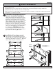
Max Load Capacity
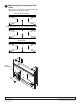
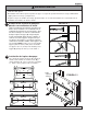
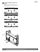
Installing Wall Plate to Metal Stud Walls for:
PA730, PP730, SA730P, SP730P, PA740, PP740, SA740P,
SP740P, SP735P, SA735P, PA735F, SP746P, SA746P, PA746F
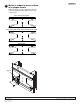
Models: WSP700, WSP701
NOTE: Read entire instruction sheet before you start installation and assembly.
Parts may appear slightly different than illustrated.
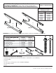
Before you begin, make sure all parts shown are included with your product.
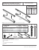
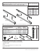
Parts List WSP700 WSP701
Description Qty. Part Numbe
r
Part Numbe
r
A
wall plate 1 024-P1050 024-P1051
B wood screw #14 x 2.5 phillips hex head 4 5S1-015-C03 5S1-015-C03
C phillips screw, 1/4 - 20 x .5 black 2 520-1209 520-1209
D toggler 1/4 -20 4 560-9708 560-9708
E phillips screw 1/4 - 20 x 2.5 black 4 520-9521 520-9521
F washe
r
4 540-9440 540-9440
B
E
D
C
A
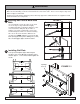
Tools Needed for Assembly
• stud fi nder ("edge to edge" stud fi nder is recommended)
• phillips screwdriver
• drill
• 1/2" (13 mm) bit for metal stud wall
• 5/32" (4 mm)
• level
WSP700
WSP701
F
WSP700
WSP701
80 lbs. (36 kg) 25 lbs. (11 kg)
SA740P SA730P
SP740P SP730P
PA740 PA730
PP740 PP730
SA746P SA735P
SP746P SP735P
PA746F PA735F