
Installation Instruction Manual

Visit the Peerless Web Site at www.peerless-av.com
8 of 9
ISSUED: 03-26-09 SHEET #: 055-9259-7 04-25-13
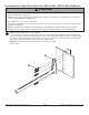
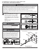
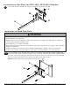
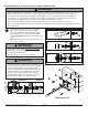
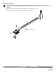
Slide adjustment tube (B) into wall arm (A) and adjust to the desired projector throw distance as shown. Using
two separate slots on wall arm (A), lock position using two M5 x 10 mm screws (D) as shown below.
Note: Securing adjustment tube (B) into wall arm (A) requires two slots.
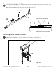
Installing PRGS projector mount to wall arm assembly: Attach PRGS projector mount (J) to adjustment tube
(B) using two 1/4-20 phillips screws (H) and two fl at washers (I) as shown in fi gure 3.1.
B
A
Assembly of Adjustment Tube
Installing PRGS Projector Mount
D
MAXIMUM EXTENSION SHOWN
TWO SCREWS REQUIRED
THROUGH TWO SLOTS
B
A
2
3
fi g. 3.1
H
I
J