
Installation Owner's manual

2 of 10
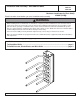
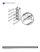
PM 610 PM 610S PM 610W
Description Qty Part # Part # Part #
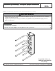
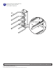
A
wall bracket 1 021-1035 021-4035 021-2035
B
shelf bracket 1 021-1027 021-4027 021-2027
C
equipment support 4 021-1031 021-4031 021-2031
D
#14 x 2.5" wood screw 5 5S1-015-C03 5S1-015-C03 5S1-015-C04
E
1/4-20 x 3/8" socket head screw 4 520-2015 520-2015 520-2028
F
VCR foam 8 599-3802 599-3802 599-3802
G
endcap 8 590-1077 590-1077 590-2072
H
5/32" allen wrench (not shown) 1 560-9706 560-9706 560-9706
Parts List
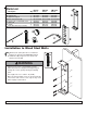
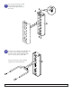
A
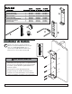
Drill five 5/32" (4 mm) dia. holes to a minimum
depth of 2.5" (64 mm) into stud center. Attach
wall bracket (A) using #14 x 2.5" (6 mm x 65
mm) wood screws (D).
D
F
Before you start make sure all parts listed are included with your product.
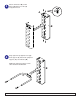
A
B
C
E
G
D
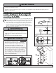
Installation to Wood Stud Walls
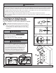
• Tighten wood screws so that wall plate is firmly
attached, but do not overtighten. Overtightening can
damage the screws, greatly reducing their holding
power.
• Never tighten in excess of 80 in • lb (9 N.M.).
• Make sure that mounting screws are anchored into the
center of the studs. The use of an "edge to edge" stud
finder is highly recommended.
WARNING
PUBLICATION: 12-20-99 SHEET#: 021-9003-3 03-23-05
Visit the Peerless Web Site at www.peerlessindustries.com For customer service call 1-800-729-0307 or 708-865-8870.