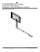
Installation and Assembly: Paramount™ Cable Management Channels Model: PCC, PCC-B, PCC-S 1 of 24 ISSUED: 04-23-08 SHEET #: 120-9046-3 09-28-12 3215 W. Web NorthSite Ave.at •www.peerless-av.com Melrose Park, IL 60160 • (800) 865-2112 or (708) 865-8870 • Fax: (708) 865-2941 • www.peerless-av.
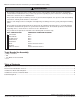
Note: Read entire instruction sheet before you start installation and assembly. WARNING • Do not begin to install your Peerless product until you have read and understood the instructions and warnings contained in this Installation Sheet. If you have any questions regarding any of the instructions or warnings, please call Peerless customer care at 1-800-865-2112.
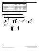
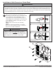
Before you begin, make sure all parts shown are included with your product. Parts List A B C D E F G Description cover corner cover mounting base cover joint end clip concrete anchor #8 x 1" phillips screw Qty.
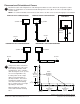
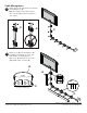
Placement and Orientation of Covers 1 Determine location and configuration of cable management that best routes cables from component to outlets. Example of configurations are shown below. Cable management covers (A) can be cut for a desired length as shown in detail 1. NOTE: It is recommended that a hacksaw be used in order to cut cable covers to desired length prior to installation.
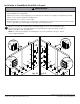
Installation to Wood/Metal Stud Wall or Drywall WARNING • Installer must verify that the supporting surface will safely support the combined load of the equipment and all attached hardware and components. • Tighten wood screws so that mounting bases are firmly attached, but do not overtighten. Overtightening can damage the screws, greatly reducing their holding power. • Never tighten in excess of 25 in. • lb (2.5 N.M.).
Installation to Solid Concrete or Cinder Block WARNING • When installing Peerless mounting bases on cinder block, verify that you have a minimum of 1-3/8" of actual concrete thickness in the hole to be used for the concrete anchors. Do not drill into mortar joints! Be sure to mount in a solid part of the block, generally 1" minimum from the side of the block. Cinder block must meet ASTM C-90 specifications.
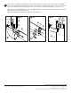
Cable Management 4 Guide cables from components into channels of mounting bases (C). Note: Be certain to route cables into the same corresponding channels and do not cross cables. CORRECT INCORRECT C 5 C C Attach covers (A) to mounting bases (C) by guiding cover flanges on covers into slide channels of mounting bases. Slide covers (A) until ends of covers are aligned with center of screws (G). A A COVER FLANGES G G C SLIDE CHANNELS C 7 of 24 Visit the Peerless Web Site at www.peerless-av.
6 Attach corner cover (B) to mounting bases (C) by guiding corner cover flanges into slide channels of mounting bases as shown in figure 6.1. Note: It may be necessary to slide covers (A) apart to allow corner cover to fit. After corner cover is attached, slide covers under corner cover until cover flanges contact flanges of corner cover. Slide apart covers (A) and align tabs of cover joint (D) with channels in mounting base (C) and attach as shown in figure 6.2. Slide covers back for a flush fit.