
Installation Instruction Manual

3 of 7
ISSUED: 1-17-11 SHEET #: 125-9179-2 07-31-12
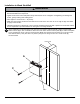
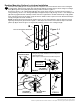
Installation to Wood Stud Wall
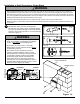
Based on their edges, draw a vertical line down each stud center. Place lock down plate (A) on wall as a template.
Level, and mark the center of the two mounting holes. Make sure that the mounting holes are on the stud center
lines. Drill two 5/32" (4 mm) dia. holes 2.5" (64 mm) deep. Secure using two #14 x 2.5" wood screws (C)
as shown below.
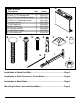
attached hardware and components.
screws, greatly reducing their holding power.
is highly recommended.
-
ers are responsible to provide hardware for other types of mounting situations
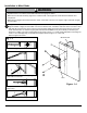
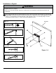
WARNING
1
C
A
Wii™