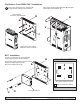
Installation and Assembly: Wall Mount with Game Console Storage Model: GC-UNV When Mounting with Model Max. Load SP850 FPS‐1000 80 lb (36 kg) 80 lb (36 kg) SA745PU SA750PU SA760PU SA770PU 70 lb (32 kg) 80 lb (36 kg) 80 lb (36 kg) 80 lb (36 kg) SA752PU SA761PU SA763PU SA771PU Mounting Directly to Screen 80 lb (36 kg) 80 lb (36 kg) 80 lb (36 kg) 80 lb (36 kg) 80 lb (36 kg) 1 of 13 Visit the Peerless Web Site at www.peerlessmounts.com © 2011 Peerless Industries, Inc. All rights reserved.
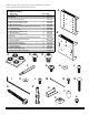
Before you begin, make sure all parts shown are included with your product. Parts may appear slightly different than illustrated.
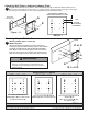
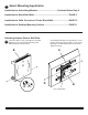
Attaching Wall Plate to dedicated adapter Plate: Using the hole pattern shown in detail 1, attach the adapter plate (A) to dedicated adapter plate with four 1 M10 x 15 mm screws (E) as shown in figure 1.1. Tighten screws using M10 penta-pin tool (F). If attaching to articulating mount use M10 x 15 mm screws (supplied with dedicated adapter plate). MOUNTING PATTERN FOR DEDICATED ADAPTER PLATES A DEDICATED ADAPTER PLATE 1 5/8" TYPICAL ADJUSTMENT INCRAMENT E Figure. 1.
Attaching Adapter Plate to SA745PU, SA750PU, SA760PU, SA770PU Universal Adapter Bracket 1 Secure adapter plate (A) to universal adapter bracket with four M10 x 15 mm screws (supplied with universal adapter bracket) as shown below.
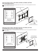
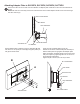
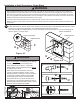
PlayStation® 3 and XBOX 360™ Installation 5 Press game console against wall plate (B) and tightly secure safety belt hardware (V). Secure four rubber feet (C) to wall plate (B) in approximate position as shown below. GAME CONSOLE (X-BOX360™ SHOWN BELOW) B B V C TM TM GAME CONSOLE MAY APPEAR DIFFERENT THAN ILLUSTRATED Wii™ Installation Secure four rubber feet (C) to wall plate (B) in approximate position as shown below.
3 Select Mounting Application Installation to Articulating Mounts....................................Continue Below Step 4 Installation to Wood Stud Wall................................................................PAGE 9 Installation to Solid Concrete or Cinder Block Wall.............................PAGE 10 Installation to Desktop Mounting Surface.............................................
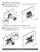
Attaching Wall Plate to SP850, FPS-1000 5 Thread two M10 x 15 mm penta-pin screws (E) into top holes of wall plate (B) leaving 1/8" space between head of screw and wall plate as shown below. Hook wall plate (B) and two exposed M10 x 15 mm penta-pin screws (E) into keyhole slots on mount. Secure with two M10 x 15 mm penta-pin screws (E) using M10 penta-pin tool (F) as shown below.
Attaching Adapter Plate to SA745PU, SA750PU, SA760PU, SA770PU 5 Remove two M5 x 20 mm screws from the rollbrake. Lift adapter plate of wall arm mount out from tilt bracket as shown. NOTE: M5 X 25 mm screw may need to be loosened a few turns to allow adapter bracket to be removed using 4 mm allen wrench (N).
Installation to Wood Stud Wall WARNING • Installer must verify that the supporting surface will safely support the combined load of the equipment and all attached hardware and components. • Tighten wood screws so that wall plate is firmly attached, but do not overtighten. Overtightening can damage the screws, greatly reducing their holding power. • Never tighten in excess of 80 in. • lb (9 N.M.). • Make sure that mounting screws are anchored into the center of the stud.
Installation to Solid Concrete or Cinder Block WARNING • When installing Peerless wall mounts on cinder block, verify that you have a minimum of 1-3/8" (35 mm) of actual concrete thickness in the hole to be used for the concrete anchors. Do not drill into mortar joints! Be sure to mount in a solid part of the block, generally 1" (25 mm) minimum from the side of the block. Cinder block must meet ASTM C-90 specifications.
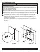
Mounting Surface Lock down Installation 4 Place wall plate (B) onto mounting surface as a template. Level, and mark the center of two rectangular mounting holes. Drill two 5/16” (8 mm) dia. holes through mounting surface. Secure using two carriage bolts (R) through wall plate (B) and mounting surface as shown in figure 4.1. Hand tighten slope nut (S) through 1/4-20 x 1 3/4" carriage bolt (R) until snug against bottom of desktop surface as shown in figure 4.2.
PlayStation® 3 and XBOX 360™ Installation 5 Press game console against wall plate (B) and tightly secure safety belt hardware (V). Secure four rubber feet (C) to wall plate (B) in approximate position as shown below. GAME CONSOLE (X-BOX360™ SHOWN BELOW) B B V C TM TM GAME CONSOLE MAY APPEAR DIFFERENT THAN ILLUSTRATED Wii™ Installation Secure four rubber feet (C) to wall plate (B) in approximate position as shown below.
6 Fasten two M8 x 15 mm screws (D) into wall plate (B) leaving 1/8" of exposed thread using 4 mm allen wrench (I) as shown below. Hook adapter plate (A) onto exposed M8 x 15 mm screws, and secure using two M8 x 15 mm screws (D) using 4 mm allen wrench (I) as shown below. Tighten all screws.