
Installation Owner manual


ISSUED: 12-01-08 SHEET #: 120-9065-2 08-18-09
Visit the Peerless Web Site at www.peerlessmounts.com For customer care call 1-800-729-0307 or 708-865-8870.
7of25
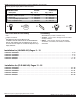
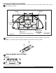
6.17
7.00
6.23
3.000
13.50
4.71
7.94
7.00
13.50
7.00
3.80
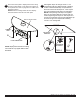
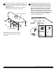
2
Slide two 1/4-20 x 1 3/4" bolts through slots on lock down plate as shown below. (supplied in HLG-452-001)
NOTE: 2 1/4" carriage bolts (ACC939) are available for use with thicker mounting surfaces.
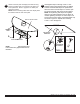
1
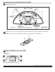
Use lock-down plate as a template to mark location of holes, point 1 and point 2, exactly 7" apart on table. Drill two
holes using a 1/4'' drill bit.
Installation(HLG452-001)52LG50DC
52LG50DC
TABLETOP
POINT1
POINT2
RUBBERFEET
(PLACEONTOPOFEXISTINGFEET)
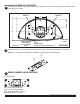
C. 52LG50DC
M5 x 12 mm phillips screws (A)
.25 ID x .5 OD x .25 spacers (B)
Place spacer (B) between lock down
plate and the base of the screen.
DISPLAYMODELHOLEPATTERN
3
LOCK-DOWN
PLATE
ENSUREPROPER
ORIENTATION
OFLOCK-DOWN
PLATE