
Installation Owner manual


ISSUED: 12-01-08 SHEET #: 120-9065-2 08-18-09
Visit the Peerless Web Site at www.peerlessmounts.com For customer care call 1-800-729-0307 or 708-865-8870.
10 of 25
BOTTOMOF
DESKTOP
5
FIG5.1
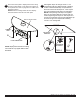
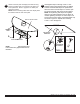
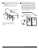
TIGHTENING
SLOPENUT
Hand tighten slope nut through 1/4-20 x 1 3/4"
carriage bolt until snug against bottom of desktop
surface. Thread another slope nut upside-down,
about two turns from rst slope nut . Insert a open
box wrench between both slope nuts and tighten.
NOTE: Avoid jamming both slope nuts together,
doing so may make it difcult to remove slope nut
used for tightening rst slope nut. After slope nut is
secure remove bottom slope nut and add plastic cap
as shown in gure 5.2. Repeat with remaining
1/4-20 x 1 3/4" carriage bolt.
FIG5.2
RUBBER
FEET
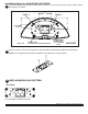
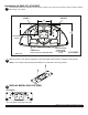
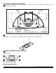
Attach lock-down plate to display base bottom using
screws provided. Refer to lock-down hole pattern for
screw placement. Refer to page three for rubber feet
placement pattern.
NOTE: Remove existing rubber feet from display
base that interfere with the lock-down plate.
NOTE: Display base stand and mounting
hole locations may appear different than
illustrated.
DISPLAY BASE STAND
D
LOCKDOWNPLATE
4