Installation and Assembly Flat-Panel Base Lock-Down Accessory Kit For LG Display Models 42LG30DC, 47LG50DC, 52LG50DC, and 42PQ30C, 50PQ30C Models: ACC942, ACC942-Q10 Maximum Display Weight: 100 lb (45.35 kg) 3215 W. North Ave. • Melrose Park, IL 60160 • (800) 729-0307 or (708) 865-8870 • Fax: (708) 865-2941 • www.peerlessmounts.
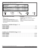
Note: Read instruction sheet before you start installation and assembly. Parts may appear slightly different than illustrated. Parts List A B C D e A Description M5 x 12 mm phillips pan screw .25 ID x .5 OD x .25 spacer rubber pad # 10 x 3/8 phillips pan TEK screw # 8 x 1/2 phillips screw Qty. 4 4 4 4 4 B ACC942 Part # 520-1027 590-1050 590-1159 520-2612 500-1011 Qty.
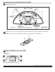
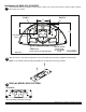
Installation Option for (HLG452-001) 42LG30DC Use lock-down plate as a template to mark location of holes, point 1 and point 2, exactly 7" apart on table. 1 holes using a 1/4'' drill bit. POINT 1 7.00 Drill two POINT 2 3.80 6.17 LOCK-DOWN PLATE TABLE TOP RUBBER FEET (PLACE ON TOP OF EXISTING FEET) ensure proper orientation of lock-down plate 42LG30DC 7.00 2 Slide two 1/4-20 x 1 3/4" bolts through slots on lock down plate as shown below.
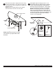
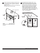
Attach lock-down plate to display base bottom using screws provided. Refer to lock-down hole pattern for screw placement. Refer to page three for rubber feet placement pattern. NOTE: Remove existing rubber feet from display base that interfere with the lock-down plate. 5 DISPLAY BASE STAND RUBBER FEET Hand tighten slope nut through 1/4-20 x 1 3/4" carriage bolt until snug against bottom of desktop surface. Thread another slope nut upside-down, about two turns from first slope nut .
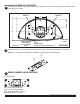
Installation (HLG452-001) 47LG50DC 1 Use lock-down plate as a template to mark location of holes, point 1 and point 2, exactly 7" apart on table. Drill two holes using a 1/4'' drill bit. POINT 1 POINT 2 7.00 3.00 6.23 13.50 LOCK-DOWN PLATE TABLE TOP 2 3 RUBBER FEET (PLACE ON TOP OF EXISTING FEET) ensure proper orientation of lock-down plate 47LG50DC Slide two 1/4-20 x 1 3/4" bolts through slots on lock down plate as shown below.
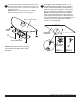
4 Attach lock-down plate to display base bottom using screws provided. Refer to lock-down hole pattern for screw placement. Refer to page five for rubber pad placement pattern. NOTE: Remove existing rubber feet from display base that interfere with the lock-down plate. Hand tighten slope nut through 1/4-20 x 1 3/4" carriage bolt until snug against bottom of desktop surface. Thread another slope nut upside-down, about two turns from first slope nut .
Installation (HLG452-001) 52LG50DC Use lock-down plate as a template to mark location of holes, point 1 and point 2, exactly 7" apart on table. 1 holes using a 1/4'' drill bit. POINT 1 Drill two POINT 2 7.00 4.71 7.94 13.50 TABLE TOP 2 ensure proper orientation of lock-down plate LOCK-DOWN PLATE RUBBER FEET (PLACE ON TOP OF EXISTING FEET) 52LG50DC Slide two 1/4-20 x 1 3/4" bolts through slots on lock down plate as shown below.
Attach lock-down plate to display base bottom using screws provided. Refer to lock-down hole pattern for screw placement. Refer to page seven for rubber pad placement pattern. NOTE: Remove existing rubber feet from display base that interfere with the lock-down plate. 4 Hand tighten slope nut through 1/4-20 x 1 3/4" carriage bolt until snug against bottom of desktop surface. Thread another slope nut upside-down, about two turns from first slope nut .
Installation Option for (HLG452-001) 42PQ30C Use lock-down plate as a template to mark location of holes, point 1 and point 2, exactly 7" apart on table. 1 holes using a 1/4'' drill bit. POINT 1 7.00 Drill two POINT 2 4.92 7.29 12.13 TABLE TOP 2 ensure proper orientation of lock-down plate LOCK-DOWN PLATE RUBBER FEET (PLACE ON TOP OF EXISTING FEET) 42PQ30C Slide two 1/4-20 x 1 3/4" bolts through slots on lock down plate as shown below.
4 Attach lock-down plate to display base bottom using screws provided. Refer to lock-down hole pattern for screw placement. Refer to page three for rubber feet placement pattern. NOTE: Remove existing rubber feet from display base that interfere with the lock-down plate. 5 DISPLAY BASE STAND RUBBER FEET Hand tighten slope nut through 1/4-20 x 1 3/4" carriage bolt until snug against bottom of desktop surface. Thread another slope nut upside-down, about two turns from first slope nut .
Installation Option for (HLG452-001) 50PQ30C Use lock-down plate as a template to mark location of holes, point 1 and point 2, exactly 7" apart on table. 1 holes using a 1/4'' drill bit. POINT 1 7.00 POINT 2 Drill two ensure proper orientation of lock-down plate 4.35 6.72 13.90 TABLE TOP 2 LOCK-DOWN PLATE RUBBER FEET (PLACE ON TOP OF EXISTING FEET) 50PQ30C Slide two 1/4-20 x 1 3/4" bolts through slots on lock down plate as shown below.
4 Attach lock-down plate to display base bottom using screws provided. Refer to lock-down hole pattern for screw placement. Refer to page three for rubber feet placement pattern. NOTE: Remove existing rubber feet from display base that interfere with the lock-down plate. 5 DISPLAY BASE STAND RUBBER FEET Hand tighten slope nut through 1/4-20 x 1 3/4" carriage bolt until snug against bottom of desktop surface. Thread another slope nut upside-down, about two turns from first slope nut .
Installation Option for (FLD-UNV-LG) 1 Position TV stand to proper location and mark front of the stand on the desktop. 2 Remove screws that hold display to the base stand as shown below. NOTE: Stand may appear different than illustrated. FRONT TV STAND BACK OF DISPLAY TOP VIEW 42LG30DC Option 1 NOTE: Use this option when optimum security is needed. Brackets may be flipped for more distance from the 3 edge of the table as shown on page 14 detail 3.
42LG30DC Option 2 NOTE: Use this option when back brackets cannot be flipped when a longer distance from the back of the table is 3 desired. Flip TV stand upside down and attach four additional rubber pads (C) over existing pads. The width is measured and located 6.4" from center line of display as shown below. Attach both front lock-down brackets to desktop using two #8 x 3/4 phillips screws and washers as shown in fig 3.1.
4 Thread four # 10 x 3/8 phillips screws (D) for option 1 or remove existing rubber pads and screws and replace them with four #8 x 1/2 phillips screws (E) for option 2 into front holes, leaving 1/8" of exposed thread. Flip desktop stand right side up and slide into front lock-down bracket so that screws in front holes locks securely into slot of front lock-down bracket as shown below.
47LG50DC Option 1 NOTE: Use this option when optimum security is needed. Brackets may be flipped for more distance from the 1 edge of the table as shown on page 17 detail 3. Flip TV stand upside down and attach four additional rubber pads (C) over existing pads. The width is measured and located 3.7" from center line of display as shown below. Attach both front lock-down brackets to desktop using two #8 x 3/4 phillips screws and washers as shown in fig 1.1.
3.35 MAX 47LG50DC Option 2 NOTE: Use this option when back brackets cannot be flipped when a longer distance from the back of the table is 1 desired. Flip TV stand upside down and attach four additional rubber pads (C)12.80 over existing pads. The width is measured and located 7.95" from center line of display as shown below. Attach both front lock-down brackets to desktop using two #8 x 3/4 phillips screws and washers as shown in fig 3.1.
2 Thread four # 10 x 3/8 phillips screws (D) for option 1 or remove existing rubber pads and screws and replace them with four #8 x 1/2 phillips screws (E) for option 2 into front holes, leaving 1/8" of exposed thread. Flip desktop stand right side up and slide into front lock-down bracket so that screws in front holes locks securely into slot of front lock-down bracket as shown below.
7.50 52LG50DC Option 1 1 NOTE: Use this option when optimum security is needed. Brackets may be flipped for more distance from the edge of the table as shown on page 20 detail 3. Flip TV stand upside down and attach four additional rubber pads (C) over existing pads or symmetrically. The width is measured and located 7.08" from center line of display as shown below. Attach both front lock-down brackets to desktop using two #8 x 3/4 phillips screws and washers as shown in fig 1.1.
3.35 MAX 52LG50DC Option 2 Use this option when back brackets cannot be flipped when a longer distance from the back of the table is 1 NOTE: 12.80 desired. Flip TV stand upside down and attach four additional rubber pads (C) over existing pads. The width is measured and located 7.95" from center line of display as shown below. Attach both front lock-down brackets to desktop using two #8 x 3/4 phillips screws and washers as shown in fig 3.1.
2 Thread four # 10 x 3/8 phillips screws (D) for option 1 or remove existing rubber pads and screws and replace them with four #8 x 1/2 phillips screws (E) for option 2 into front holes, leaving 7/16" of exposed thread. Flip desktop stand right side up and slide into front lock-down bracket so that screws in front holes locks securely into slot of front lock-down bracket as shown below.
42PQ30C NOTE: Use this option when optimum security is needed. Brackets may be flipped for more distance from the 1 edge of the table as shown below. Flip TV stand upside down and attach four additional rubber pads (C) over existing pads. The width is measured and located 5.75" from center line of display as shown below. Attach both front lock-down brackets to desktop using two #8 x 3/4 phillips screws and washers as shown in fig 1.1.
2 Thread four # 10 x 3/8 phillips screws (D) for option 1 or remove existing rubber pads and screws and replace them with four #8 x 1/2 phillips screws (E) for option 2 into front holes, leaving 1/8" of exposed thread. Flip desktop stand right side up and slide into front lock-down bracket so that screws in front holes locks securely into slot of front lock-down bracket as shown below.
50PQ50C NOTE: Use this option when optimum security is needed. Brackets may be flipped for more distance from the 1 edge of the table as shown below. Flip TV stand upside down and attach four additional rubber pads (C) over existing pads. The width is measured and located 6.5" from center line of display as shown below. Attach both front lock-down brackets to desktop using two #8 x 3/4 phillips screws and washers as shown in fig 1.1.
2 Thread four # 10 x 3/8 phillips screws (D) for option 1 or remove existing rubber pads and screws and replace them with four #8 x 1/2 phillips screws (E) for option 2 into front holes, leaving 1/8" of exposed thread. Flip desktop stand right side up and slide into front lock-down bracket so that screws in front holes locks securely into slot of front lock-down bracket as shown below.