
Installation Manual
1 of 2
SUPERSEDING COPY 200-9194revA 03-28-01/ m.b.
ISSUED: 05-16-08 SHEET #: 120-9047-3 09-19-08
Visit the Peerless Web Site at www.peerlessindustries.com For customer service call 1-800-729-0307 or 708-865-8870.
Note: Some parts may appear slightly different than illustrated.
Before you start make sure all parts listed are included with your product.
IMPORTANT! Read instruction sheet before you start installation and assembly.
To prevent scratching the screen, set a cloth on
a at, level surface that will support the weight of
the screen. Place screen face side down. Refer
to screen manufacturer's instructions or customer
service, for removing any knobs, base, cover, or
screw(s) on the back of the screen to prepare
mounting. These need to be removed to allow
the adapter brackets to be attached.
Place and center M10 adapter brackets (A) over
mounting holes on back of screen to locate point
of attachment.
NOTE: One M10 adapter bracket (A) must be
used for each screen mounting hole. If screen
has more than four screen mounting holes, ad-
ditional M10 adapter brackets are required.
A
1
Installation and Assembly:
M10 Adapter Brackets
Model: ACC937, ACC937-S
C
E
B
D
A
CC937
A
CC937-S
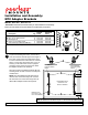
Description Qt
y
. Part # Part #
A
M10 adapter bracket 4 201-1562 201-4562
B
M6 x 12 mm phillips screw 12 520-1128 520-1128
C
M6 flanged nut 12 530-1048 530-1048
D
M10 x 15 mm phillips screw 4 520-1305 520-1305
E
multi-washer (included with ONE-TP) 4 580-1036 580-1036
Parts List
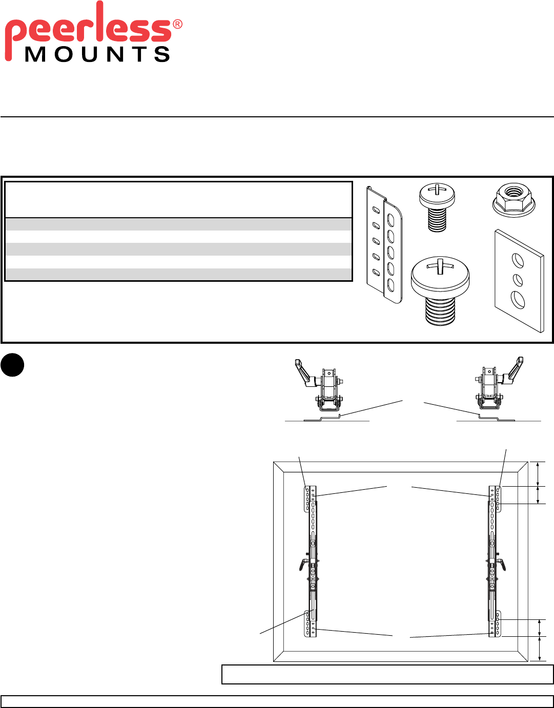
CENTER BRACKETS
VERTICALLY ON
BACK OF SCREEN
X
X
NOTE: Refer to page 4 for adjustments of top extension bracket.
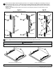
To prevent scratching the screen, set a cloth on a at, level surface that will support the weight of the screen.
Place screen face side down. Refer to screen manufacturers instructions or customer service, for removing any
knobs, base, cover, or screw(s) on the back of the screen to prepare mounting. These need to be removed to
allow the adapter brackets to be attached. Select the small, medium, large or extra large screws from the bafed
fastener pack then attach tilt brackets to screen following gure 2.3 or 2.4.
NOTE: Be sure to attach tilt brackets with knobs facing outward as in gure 2.1.
NOTE: Top and bottom mounting holes must be used for attaching brackets. Middle holes should also be used
where the fasteners and screens allow. Verify that all holes are properly aligned, and then tighten screws using a
phillips screwdriver.
PLACE FLANGE
OVER MOUNTING
HOLES
PLACE FLANGE
OVER MOUNTING
HOLES
Note: "X" dimensions should be equal. "Y" dimensions should be equal.
Y
Y
A
A
A
BRACKETS DO
NOT HAVE TO BE
FULLY EXTENDED