
Install Instructions

© Copyright 2010 PECO, Inc. All Rights Reserved P/N 68798 3220-1449 Rev2 Page 2
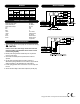
WhitewithOrangeStripe FanHigh
WhitewithRedStripe FanMedium
WhitewithBrownStripe FanLow
Red Heat
Blue Cool
Black L1
Yellow L2orNeutral
Orange SwitchedPower
Violet FanSupply
Brown RemoteProbe1
Brown RemoteProbe2
*Ifapplicable
1.Tousearemotesensor,removejumperJP-1todisablelocalsensing.
2.Remoteprobewiringshouldbelocatedawayfromanyelectrical
motors
orpowerwiring
3.Someunitsareinternallywiredforpermanentfancontinuous
operation.
4.OnunitswithaFanSupplyinputtheoperationofthefanis
determined
bywiringconnection.Forfancontinuous,jumpertheFan
Supply
input(TB2-5)totheSwitchedPoweroutput(TB3-3).
5.Forfancyclingoperationwithacallforheatorcool,afanrelaymust
be
used.
6.Observeelectricalratings.
Thermostatic
outputsarepilotdutyonly.
Voltage
Rating
Inductive
FLA LRA
Resistive
Amps
Pilot
Duty
Thermostatic
Switching
24 VAC
120 VAC
240 VAC
277 VAC
N.A. N.A. N.A. 24 VA 10 VA
5.8 34.8 6.0 125 VA 20 VA
20 VA
20 VA
125 VA
125 VA
2.9 17.4 5.0
2.4 14.4 4.2
FAN AND SYSTEM SWITCHES
▲