
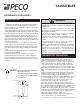
Install Instructions

© Copyright 2005 PECO, Inc. All Rights Reserved P/N 68745 3220-1407 Rev0 Page 2
White with Orange Stripe Fan High
White with Red Stripe Fan Med.
White with Brown Stripe Fan Low
Red Heat
Blue Cool
Black L1
Yellow L2 or Neutral
Orange Switched Power
Violet Fan Supply
Brown Remote Probe
Brown Remote Probe
*If applicable
Voltage
Rating
Inductive
FLA LRA
Resistive
Amps
Pilot
Duty
Thermostatic
Switching
24 VAC
120 VAC
240 VAC
277 VAC
N.A. N.A. N.A. 24 VA 10 VA
5.8 34.8 6.0 125 VA 20 VA
20 VA
20 VA
125 VA
125 VA
2.9 17.4 5.0
2.4 14.4 4.2
FAN AND SYSTEM SWITCHES
APPLICATION NOTES
RATINGS
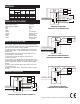
1. To use a remote sensor, remove jumper JP-1 to disable
local sensing. Failure to remove JP-1 when using a remote
sensor will cause improper operation of the thermostat. Some
units do not have remote sensing capability.
2. Units with remote sensing capability have a four position
terminal block at TB1. If TB1 is two position the unit is local
sensing only.
3. Remote probe wiring should be located away from any
electrical motors or power wiring
4. Some units are internally wired for permanent fan
continuous operation.
5. On units with a Fan Supply input the operation of the fan is
determined by wiring connection. For fan continuous, jumper
the Fan Supply input (TB2-5) to the Switched Power output
(TB3-3).
6. For fan cycling operation with a call for heat or cool, a fan
relay must be used.
7. Observe electrical ratings. Thermostatic outputs are pilot
duty only.
1
2
4
3
1
2
3
5
1
2
3
4
TB1
TB2
TB3
TB1-2
NO CONNECTION
REMOTE PROBE 2
REMOTE PROBE 1
L2 or NEUTRAL
TB1-3
TB1-4
TB1-1
FAN
COOL
OUTPUT
HEAT
OUTPUT
TB2-3
FAN HIGH
FAN LOW
FAN MED
L1
FAN SUPPLY
TB2-2
TB2-1
TB2-4
TB2-5
TB3-3
CONNECT
FOR FAN
CONTINUOUS
TB3-2
TB3-1
SWITCHED POWER
5
UNITS WITH REMOTE SENSING CAPABILITY
1
2
3
1
2
5
1
2
3
4
TB1
TB2
TB3
NO CONNECTION
L2 or NEUTRAL
TB1-3
TB1-4
FAN
COOL
OUTPUT
HEAT
OUTPUT
TB2-3
FAN HIGH
FAN LOW
FAN MED
L1
FAN SUPPLY
TB2-2
TB2-1
TB2-4
TB2-5
TB3-3
CONNECT
FOR FAN
CONTINUOUS
TB3-2
TB3-1
SWITCHED POWER
UNITS WITH SWITCHES
USED FOR LOCAL SENSING ONLY
TB3-1
COOL
OUTPUT
HEAT
OUTPUT
1
2
4
3
1
2
3
TB1
TB3
L1
TB3-3
TB3-2
TB1-2
NO CONNECTION
REMOTE PROBE 2
REMOTE PROBE 1
L2 or NEUTRAL
TB1-3
TB1-4
TB1-1
UNITS WITH NO SWITCHES WITH
LOCAL/REMOTE SENSING CAPABILITY
COOL
OUTPUT
HEAT
OUTPUT
1
2
3
1
2
TB1
TB3
L1
TB3-3
TB3-2
TB3-1
NO CONNECTION
L2 or NEUTRAL
TB1-3
TB1-4
UNITS WITH NO SWITCHES
USED FOR LOCAL SENSING ONLY
WIRE LEAD COLORS*
WIRING DIAGRAM