
Product Data


5
Seasonal Changeover Sensor
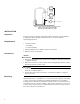
When installing the seasonal changeover sensor strap on the sensor to the main coil input
or a pipe that will determine the fluid temperature of the coil. If a well is available use thermal
grease for a faster temperature response. Insulate the entire sensor and pipe two inches
before and after the sensor for a total of approximately six inches. This insulation is used to
decrease the affect of ambient temperature upon the sensor.
Remote Sensor
Install the sensor in a location that will measure only the temperature to be sensed without
any external heating or cooling sources influencing the sensor. Examples of sources to
avoid are direct sunlight, mounting the sensor too high or too low on a wall, or any areas in
ducts that have dead air movement or un-mixed air. Be aware of room stratification and air
movement when determining the sensor location.
Wiring Notes
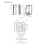
When using the optional remote sensor, remove pin pair jumper cap JP1 (Figure-9).
Removing jumper JP1 disables the onboard sensor. Failure to remove jumper JP1 will
provide two sensor inputs. The thermostat will not function properly. Run the remote sensor
wiring away from any electrical motors or power wiring. Failure to do so may result in poor
thermostat performance due to electrical noise.
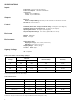
An external line voltage relay is not need with 3-speed fan applications unless the current
exceeds the values noted in Table-1. System and fan switch voltage must be the same.
For fan cycling operation with a call for heating or cooling, a fan relay needs to be inserted.
For a two pipe heating and cooling application, an external auto seasonal changeover switch
(680-243-6) must be connected to TB3-1 and TB3-2. This assures proper control depending
on the temperature of the controlling media.
In all applications run the sensor wire away from any electronic noise generating devices,
such as motors, fluorescent lights and microwaves. Do not run in parallel to line voltage
wiring. The maximum length of non-shielded sensor wire should not exceed 25 ft. Even if
the sensor wire is not near any noise generating devices, it still acts like an antenna and
picks up background noise that may affect the temperature measurement.
In an electronic noisy environment or if the sensor wire must be close to noise generating
devices, always use shielded wire and connect the shielding to an earth ground. Avoid
electronic noise generating devices even if using shielded cable. The shielded sensor wire
should not exceed 100 ft. in length and should be properly grounded.
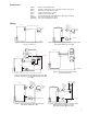
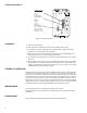
Figure-8 Mounting.