
Product Data


4
INSTALLATION
Inspection
Inspect the package for damage. If damaged, notify the appropriate carrier immediately.
If undamaged, open the package and inspect the device for obvious damage.
Return damaged products.
Requirements
• Tools (not provided)
— Screwdriver
— Volt ohm multimeter
• Training: Installer must be a qualified, experienced technician
• Other accessories as appropriate
Precautions
General
▼
W A R N I N G
• Electrical shock hazard! Disconnect power before installation to prevent electrical shock
or equipment damage.
• Make all connections in accordance with the electrical wiring diagram and in accordance
with national and local electrical codes.
▼
C A U T I O N
• Avoid electrical noise interference. Do not install near large conductors, electrical
machinery, or welding equipment.
• Avoid locations where excessive moisture, corrosive fumes, vibration, or explosive
vapors are present.
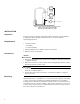
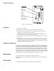
Mounting
Mount the T155 series to a standard 2 x 4 in. electrical box. Refer to Figure-8. If mounting
to 4 x 4 in. electrical box use adapter plate (#65345). Standard holes are provided for
mounting purposes. Mount the thermostat five feet above the floor on an inside wall. Do not
mount near a heat source (lamp or sunlight), or behind a door or furniture. Do not mount on
a surface that exceeds 130°F (55°C). Insulate behind thermostat if necessary to protect it
from cold or warm air from outside areas.
4
3
2
1
1
2
3
1
2
3
4
5
TB1
TB2
TB3
L2 OR NEUTRAL
Tb155-010
LOW
MED
L1 (HOT)
FAN
HI
COOLING
VALVE
HEATING
VALVE
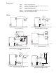
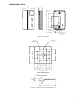
Figure-7 Typical 4-Pipe Heating/Cooling Fan Runs
Continuously with System Switch On.
With System Switch Off, Fan is Off.