
Quick Start Guide

© COPYRIGHT 2014 PECO ASTRONICS. ALL RIGHTS RESERVED. P/N 70931 3220-2323 REV 00
1
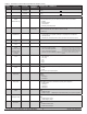
Next
Next
Next
Next
Next
Done
More >Clock
Next Go Back
Done
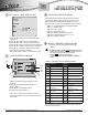
Note: Upon completion of installation, remove
the plastic insulator tab from the back side of the
thermostat.
WARNING: DISCONNECT POWER BEFORE BEGINNING INSTALLATION.
• CAUTION: Use copper wire only. Insulate or wire-nut all unused leads.
• Use care to avoid electrostatic discharge to thermostat
• CAUTION: Do not connect unused wires together
• ALL ELECTRICAL LOADS MUST BE CONNECTED TO TERMINAL C
(24 VAC).
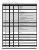
Fan Coil (Conventional) Heat Pump
C 24 VAC, Unswitched side C 24 VAC, Unswitched side
W1 Stage 1 Heat B/O Reversing Valve
W2 Stage 2 Heat AUX Auxiliary Heat (Stage 3)
G FAN G FAN
A Economizer/Damper/Humidity A Economizer/Damper/Humidity
E Stage 3 Heat E Emergency Heat
Y1 Stage 1 Cool Y1 Compressor Stage 1/Heat/Cool 1
Y2 Stage 2 Cool (or Dehumidify) Y2
Compressor Stage 2/Heat/Cool 2
(or Dehumidify)
RH
24 VAC Power for heating,
switched side
RH
24 VAC Power for heating,
switched side
RC
24 VAC Power for cooling,
switched side
RC
24 VAC Power for cooling,
switched side
SC Sensor Common SC Sensor Common
S1 Indoor Remote Sensor S1 Indoor Remote Sensor
S2 Occupancy Setback Input* S2 Occupancy Setback Input
S3 Outdoor Remote Sensor S3 Outdoor Remote Sensor
▲
*Contact PECO to learn more about Occupancy Setback
Input sensor applications.
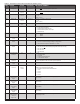
Service
Menu
QUICK START GUIDE
PERFORMANCE PRO T8000
Insulator
Tab
Current
option
AN ASTRONICS COMPANY