
Install Instructions

9
© COPYRIGHT 2010 PECO, INC. ALL RIGHTS RESERVED. P/N 70413 3220-2260 REV 01
Creating a PIN access code allows the installer to restrict access to Service Menus. First,
a PIN access must be enabled in Service Menu 341; second, a three-digit code must be
created in Service Menu 342. After these two Service Menus are properly con gured, the
thermostat requires the user to enter a PIN access code to enter the Service Menus.
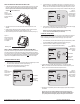
1. On the thermostat, press the lower left and lower right keys simultaneously for about
ve seconds. Next, Go Back, and Done appear (see Fig. 15).
2. Press Next until Service Menu 341 (Enable/Disable PIN Access) appears in the
display. (Default value appears below Service Menu.)
3. In Service Menu 341, press ▲/ ▼to change digit ( ashing) value to “01” (see Fig. 16).
4. Press Next.
5. In Service Menu 342, press ▲/ ▼adjust values and create a three-digit PIN access
code. The ashing three-digit code appears in the clock area (see Fig. 16).
6. Press Done when nished.
Enter the PIN access code upon entering the Service Menus. Note: Flashing digit is active;
it is changed using the ▲/ ▼keys. The active (editable) digit moves from right to left.
1. On the thermostat, press the lower left and lower right keys simultaneously for about
ve seconds. Flashing three-digit code, Next, and Done appear (see Fig. 17).
2. Press ▲/ ▼to change value of digit furthest to the right, then press Next.
3. Press ▲/ ▼to change value of digit in middle, then press Next.
4. Press ▲/ ▼to change value of digit furthest to left, then press Done.
: After step 4 is complete, user is allowed access to Service Menus. Next,
Go Back,
Done, and Service Menu 100 appear.
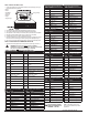
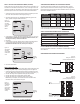
The following T8000 Series compatible sensors are available from PECO, providing
optimal control of the environment. In addition, following are sensor wiring diagrams for
temperature averaging, Indoor Remote Zone Sensor installation instructions, and Outdoor
Remote Sensor installation instructions.
Indoor Remote
Sensor
SP155-017 69308 S1
Occupancy Sensor
SB200-001 68375 S2
Outdoor Remote
Sensor
-- 70327 S3
To learn more about the bene ts of PECO sensors visit .
Or call 1-800-874-8547 to speak with a service representative.
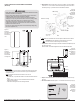
000 - 150 feet 22 gauge
151 - 240 feet 20 gauge
241- 385 feet 18 gauge
386 - 610 feet 16 gauge
611 -970 feet 14 gauge
Use appropriate wire for outdoor use.
Please use the installation instructions for the SB200-001 to mount the PECO Occupancy
Sensor SB200-001.
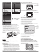
Figure 18.
Wiring four SP155-017
(10K ohm) temperature sensors.
Figure 19.
Wiring nine SP155-017
(10K ohm) temperature sensors.
Figure 15.
Service Menu
341 allows
user to restrict
access to
Service
Menus.
Figure 16.
Service Menu
342 allows
user to create
a PIN access
code.
Flashing
three-digit
code
Figure 17.
PIN access
code fl ashes
when user
enters Service
Menus (after
enabling PIN
access).
Flashing
three-digit
code