
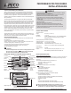
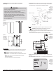
Install Instructions

© COPYRIGHT 2010 PECO, INC. ALL RIGHTS RESERVED. P/N 70478 3220-2267 REV 00
5
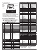
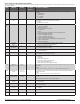
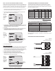
To access Service Menus, simultaneously press lower left and lower right keys. Changed values are automatically retained. Service Menu availability is dependent upon system type and
upon system conguration.
Schedule Format 0-3 1 Select the schedule format on the T8000 Series. (Menu not available on non-programmable
thermostats.)
0 = nonprogrammable
1 = programmable
2 = 5-1-1 schedule
3 = 5-2 schedule
Daylight-Saving
Time
0,1 0 Select daylight-saving time as it follows standard format in U.S.: It begins second Sunday of March at
2:00 AM and ends on the rst Sunday of November at 2:00 AM.
0 = Disabled
1 = Enabled (2007 U.S. Format)
System Type 1-13 1 Select the appropriate system conguration (determines available Service Menus).
1 = 1 Heat/1 Cool conventional
2 = 1 Heat/1 Cool heat pump
3 = Heat only without fan (2-wire systems)
4 = Heat only with fan
5 = Cool only
6 = 2 Heat/1 Cool heat pump (with auxiliary heat) and Emergency (Em) heat
7 = 2 Heat/2 Cool multistage conventional
8 = 2 Heat/ 1 Cool multistage conventional
9 = 1 Heat/ 2 Cool multistage conventional
10 = 2 Heat/ 2 Cool heat pump (no auxiliary heat)
11= 3 Heat/ 2 Cool heat pump (with auxiliary heat) and Emergency (Em) heat
12 = 3 Heat/ 1 Cool conventional
13= 3 Heat/ 2 Cool conventional
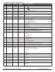
Fan Control
(heating)
0,1 0 0 = Fossil Fuel: Gas/Oil/Propane heat (equipment controls heating fan)
1 = Electric Furnace (thermostat controls heating fan)
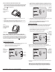
Changeover valve
(B/O terminal)
0,1 0 0 = B/O terminal controls valve in cooling
1 = B/O terminal controls valve in heating
Auxiliary Heat 0,1 0 0 = Electric backup heat
1 = Fossil fuel backup heat
Backlight 0,1 0 0 = Backlight temporarily on
1 = Backlight always on (low intensity, 24V only)
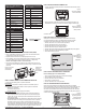
Remote Sensor 0-5 0 Select sensor if used. Contact PECO for information on the T8000 Series Indoor Remote Zone Sensor.
0 = No Sensor
1 = Indoor Sensor
2 = Outdoor Sensor display only
3 = Outdoor Sensor display and lockout control
4 = Indoor, Outdoor Sensor display only
5 = Indoor, Outdoor Sensor display and lockout control
Heat Pump
Compressor Lockout
0-45°F
(-18°C - 7°C)
0 If an outside sensor is used, the compressor will be locked out when the outside air temp is below the
value selected.
0 = None
15°F( -9°C); 20°F (-7°C); 25°F ( -4°C); 30°F ( -1°C); 35°F (2°C); 40°F (4°C); 45°F (7°C)
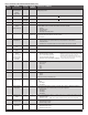
Heat Pump Auxiliary
Lockout
0- 60°F
(-18°C - 15°C)
0 If an outside sensor is used, the auxiliary heat will be locked out when the outside air temperature is
above the value selected.
0 = None
40°F (4°C); 45°F (7°C); 50°F (10°C); 55°F (13°C); 60°F (16°C)
Furnace Filter
Change Reminder
0; 30; 60; 90;
120; 365
0 Set a lter reminder timer; appears on digital display when timer expires (if programmed).
0 = Off
10 days; 30 days; 60 days; 90 days; 120 days; 365 days
Number of Program
Periods
2; 4 events 4 2 = 2 events per day
4 = 4 events per day
Clock format 12 or 24 Hours 12 12 = 12-hour clock mode
24 = 24-hour clock mode
Temperature Format
(°F or °C)
0,1 1 0 = Celsius
1 = Fahrenheit
Fan Off Delay Heat 0-99 Seconds 0 Select the amount of time (in seconds) that the fan will run after the thermostat heat outputs are turned
off.
Fan Off Delay Cool 0-99 Seconds 0
Select the amount of time (in seconds) that the fan will run after the thermostat
cool outputs are turned
off.