
Install Instructions

4
© COPYRIGHT 2010 PECO, INC. ALL RIGHTS RESERVED. P/N 70413 3220-2260 REV 01
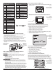
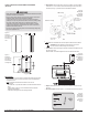
1. Position the thermostat slightly above the mounted wallplate (see Fig. 9), then secure
the hooks on the back side of the thermostat to the hinge pockets on the wallplate.
2. Align the pins on the back side of the thermostat with the terminal blocks on the
wallplate.
3. Gently bring down the thermostat onto the wallplate so the pins on the back of the
thermostat t into the terminal blocks on the wallplate (see Fig. 10).
4. Attach the retaining screw to the underside of the thermostat as shown (see Fig. 10).
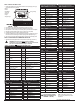
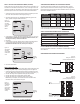
System test veri cation is highly recommended to verify thermostat operation. Follow at
least one procedure in the system tests below. Refer to the Service Menus (see Table 2)
for more system tests. For all system tests, press to continue to the following system
test, which is the next available Service Menu. Press only if nished performing all
system tests. Pressing exits the Service Menus and turns off all active outputs.
1. On the thermostat, press the lower left and lower right keys simultaneously for about
ve seconds. Next,
Go Back, and Done appear (see Fig. 11).
2. Press Next until Service Menu 610 appears in the display.
(Default value “00” appears below Service Menu.)
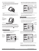
3. In Service Menu 610, press ▲/ ▼to select option “01,” Heat Stage 1 (see Fig.12).
: If 01 is selected, the thermostat will activate the associated output for up to 10
minutes. The user should observe that the fan output (with heat) turns on. The user
may also test more stages of heat according to what is available for the system type.
4. Press Done to complete the system test and exit the Service Menus. After verifying
the system test, the outputs are disabled and the fan will stop.
Next
The following instructions assume that the user enters the Service Menus from the Home
Display; it does not assume that the user has followed in sequence from the previous
section. If continuing from the previous section on this page, skip to Step 2 below.
1. On the thermostat, press the lower left and lower right keys simultaneously for about
ve seconds. : Next,
Go Back, and Done appear (see Fig. 13).
2. Press Next until Service Menu 620 appears in the display.
(The default value “00” for appears below Service Menu.)
3. In Service Menu 620, press ▲/ ▼to select option “01” (to enable fan output).
If 01 is selected, the thermostat will activate the associated output for up to 10
minutes. The user should observe that the fan output will turn on.
4. Press Done to complete the system test. After verifying the system tests, the outputs
are disabled.
Next
Figure 12.
Press Done to
complete test and
exit Service Menus
or Next to continue
to the next test.
Figure 14.
Press Done to
complete testing
and exit Service
Menus, or Next to
continue tests.
Figure 11.
Service Menu 610
allows user to
perform System
Test (Heat).
Service Menu
Default value
(appears
automatically)
Figure 13.
Service Menu 620
allows user to
perform a System
Test Fan.
Service Menu
Default value
(appears
automatically)
Figure 9.
Secure the hooks
on the back side of
the thermostat to the
wallplate.
Retaining screw
Figure 10.
Mount the thermostat
so pins on back fi t into
the terminal blocks on
the wallplate.