
Install Instructions

© COPYRIGHT 2010 PECO, INC. ALL RIGHTS RESERVED. P/N 70478 3220-2267 REV 00
3
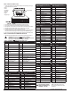
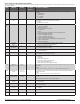
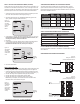
System Type 11: 3H/2C Heat Pump System Type 12: 3H/1C Conventional
TERM Function TERM Function
C Common C Common
B/O Reversing Valve W1 Heat 1
AUX Auxiliary Heat W2 Heat 2
G Fan G Fan
A Economizer/Damper A Economizer/Damper
E Emergency Heat E Heat 3
Y1 Compressor 1 Y1 Cool 1
Y2 Compressor 2 Y2
RH Power for Heating RH Power for Heating
RC Power for Cooling RC Power for Cooling
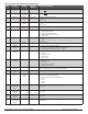
System Type 13: 3H/2C Conventional
TERM Function
C Common
W1 Heat 1
W2 Heat 2
G Fan
A Economizer/Damper
E Heat 3
Y1 Cool 1
Y2 Cool 2
RH Power for Heating
RC Power for Cooling
2. Using a small athead screwdriver, loosen the screws on the terminal blocks that
correspond to the system type (see Table 1).
3. Strip the insulation of each wire at a proper length (about 1/4” or 64 cm).
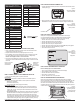
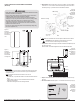
4. On the wallplate, insert wires into the terminal blocks that correspond to the system
type, then re-tighten each screw for each terminal (see Fig. 4, enlarged area).
5. Assure that no uninsulated wires are exposed: Cap off and place a wire-nut on any
unused wires. Assure that the attached wires t into the cavity on the back side of the
thermostat.
1. Choose from the following options to power the thermostat.
The T8000 Series will operate on 24VAC power and/or two AA batteries (both are
recommended). Choose from three methods to connect power to the thermostat.
• Batteries only (AA alkaline)
• 24 VAC direct connection only
• 24 VAC with AA battery backup (highly recommended)
: Connect the common side of the transformer to
the “C” screw terminal of the thermostat wallplate. Assure that the metal jumper
connects “RC” and “RH.” Connect power side to the RC/RH and assure that the
jumper remains in place.
The T8000 Series is shipped with a jumper connecting
terminals RH and RC. If the heating and cooling equipment do not use separate
transformers, leave this jumper in place. If separate transformers are required,
remove this jumper. With the jumper removed, connect RC to the power side of the
cooling transformer. Connect RH to the power side of the heating transformer; then
connect both the heating and cooling commons together to terminal C (Common).
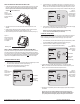
1. Insert two AA batteries (included) into the back compartment of the thermostat, where
indicated (see Fig. 5).
2. Remove the plastic insulator tab from the back side of the thermostat (see Fig. 6).
IMPORTANT: The insulator tab must be removed before setting the real-time clock.
When power is rst applied to the thermostat, it will activate the clock display.
It is recommended that time and day are entered before performing advanced
con guration. Follow the procedure below to set the clock, month, and day.
1. Press ▲/ ▼ to select 12 or 24 HR mode, then press Next.
2. Press ▲/ ▼to select clock hour, then press Next.
3. Press ▲/▼to select clock minutes, then press Next.
4. Press ▲/ ▼ to select clock year, then press Next.
5. Press ▲/ ▼ to select current month, then press Next. : Mo (month) appears.
6. Press ▲/ ▼to select current date. : Days appears.
7. Press Done to nish clock mode.
1. Press any part of the touchscreen area to enter the Home Display.
2. Press System to enter system settings.
3. Press ▲/ ▼to select “Off,” then press Done.
4. Press Fan key to enter fan mode.
5. Press ▲/ ▼to select “Auto,” then press Done.
Perform advanced con guration before attaching the thermostat to the wallplate.
Advanced con guration is done by simultaneously pressing the lower left and lower right
keys for about ve seconds (See Fig. 8), which gives user access to Service Menus.
Use Table 2 of this Installation Guide to set each desired Service Menu item. Advanced
con guration allows the user to con gure the thermostat to match the system type and to
customize several thermostat settings.
▲
Figure 5.
Insert two AA batteries
in back of thermostat.
Figure 6.
Remove the insulator
tab from thermostat
before operation.
Insulator tab
Figure 4. Insert wires
into appropriate
terminal blocks.
Enlarged area
shows wire
insertion point
above terminal
block.
Figure 7.
Clock must be set
before performing
advanced
confi guration.
Figure 8.
Access Service Menus
by pressing the lower
right and lower left
keys simultaneously.
customize several thermostat settings.