
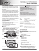
Install Instructions

© COPYRIGHT 2010 PECO, INC. ALL RIGHTS RESERVED. P/N 70478 3220-2267 REV 00
2
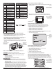
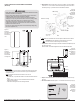
1. Position the wallplate on the wall with the directional arrow pointing up (see Fig. 3)
and terminal blocks facing outward.
2. Pull equipment wires through the wallplate wiring passage (see Fig. 3).
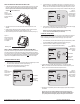
3. Use a level to determine the best horizontal wallplate mounting position.
4. Mark positions of screw holes (two at minimum) with a pencil and remove wallplate.
5. Drill holes at pencil-marked locations (3/16” for drywall, 7/32” for plaster).
6. Insert the wall anchors in the holes, tapping them into place.
7. Mount the wallplate onto the wall and insert screws through mounting holes. Assure
that all loose wires come through the center opening of the wallplate (see Fig. 3).
8. Cap off any unused wires and terminate properly according to local building codes.
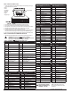
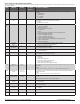
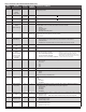
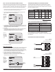
1. Select the terminal designations that correspond to the system type (see Table 1).
Conventional Terminal Letters Heat Pump Terminal Letters
Unswitched side, 24 VAC
Unswitched side, 24 VAC
Stage 1 Heat
Reversing Valve
Stage 2 Heat
Auxiliary (Stage 3 Heat)
Fan
Fan
Economizer/Damper/
Humidity
Economizer/Damper/
Humidity
Stage 3 Heat
Emergency Heat
Stage 1 Cool
Compressor Stage 1, Heat /Cool 1
Stage 2 Cool (or Dehumidify)
Compressor Stage 2, Heat /Cool 2
(or Dehumidify)
Power for heating,
switched side, 24 VAC
Power for heating,
switched side, 24 VAC
Power for cooling,
switched side, 24 VAC
Power for cooling,
switched side, 24 VAC
Sensor Common
Sensor Common
Indoor Remote Sensor
Indoor Remote Sensor
Occupancy Setback Input*
Occupancy Setback Input*
Outdoor Remote Sensor
Outdoor Remote Sensor
System Type 1: 1H/1C Conventional System Type 2: 1H/1C Heat Pump
TERM Function TERM Function
C Common C Common
W1 Heat B/O Reversing Valve
W2 AUX
G Fan G Fan
A Economizer/Damper A Economizer/Damper
E E
Y1 Cool Y1 Compressor
Y2 Y2
RH Power for Heating RH Power for Heating
RC Power for Cooling RC Power for Cooling
System Type 3: Heat only (without fan) System Type 4: Heat only with fan
TERM Function TERM Function
C Common C Common
W1 Heat W1 Heat
W2 W2
G G Fan
A Economizer/Damper A Economizer/Damper
E E
Y1 Y1
Y2 Y2
RH Power for Heating RH Power for Heating
RC RC
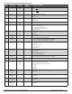
System Type 5: Cool only System Type 6: 2H/1C Heat Pump (Aux.)
TERM Function TERM Function
C Common C Common
W1 B/O Reversing Valve
W2 AUX Auxiliary Heat
G Fan G Fan
A Economizer/Damper A Economizer/Damper
E E Emergency Heat
Y1 Cool Y1 Compressor
Y2 Y2
RH Power for Heating RH Power for Heating
RC Power for Cooling RC Power for Cooling
System Type 7: 2H/2C Conventional System Type 8: 2H/1C Conventional
TERM Function TERM Function
C Common C Common
W1 Heat 1 W1 Heat 1
W2 Heat 2 W2 Heat 2
G Fan G Fan
A Economizer/Damper A Economizer/Damper
E E
Y1 Cool 1 Y1 Cool
Y2 Cool 2 Y2
RH Power for Heating RH Power for Heating
RC Power for Cooling RC Power for Cooling
System Type 9: 1H/2C Conventional System Type 10: 2H/2C Heat Pump
TERM Function TERM Function
C Common C Common
W1 Heat B/O Reversing Valve
W2 AUX
G Fan G Fan
A Economizer/Damper A Economizer/Damper
E E
Y1 Cool 1 Y1 Compressor 1
Y2 Cool 2 Y2 Compressor 2
RH Power for Heating RH Power for Heating
RC Power for Cooling RC Power for Cooling
: Contact PECO to learn more
about Occupancy Setback Input sensor
applications.
i
▲
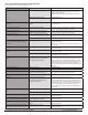
Figure 3:
Position
the wallplate
on the wall.
Pull wires
through
wiring passage.
wiring passage
terminal blocks enlarged