
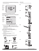
Install Instructions

© COPYRIGHT 2010 PECO, INC. ALL RIGHTS RESERVED. P/N 70478 3220-2267 REV 00
12
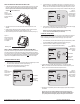
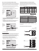
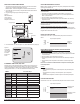
1. Wire the PECO Outdoor Remote Sensor (P/N 70327) to Terminal S3 and Sensor
Common (SC) on the thermostat backplate (see Fig. 27).
: See Table 1 for terminal designations for the Indoor Remote Zone Sensor.
2. Assure that Step 6 (previous section) is complete and the PECO Outdoor Remote
Sensor is secure.
3. Plug the wiring passage using non-hardening caulk or putty.
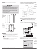
4. Go to Service Menu 170, select from options 2-5, Outdoor Remote Sensor (see Fig.28).
Allow the outdoor or indoor temperature sensor to absorb the air for a minimum of ve
minutes before taking a reading. See Service Menu 370 for controls the Economizer/
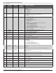
Outside air damper behavior. Table 5 shows the Economizer/TOD behaviors of available
settings (Options include 0-4; 0 = OFF, which disables the Economizer function).
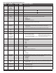
Occupied N/A ON Continuously ON Continuously
Unoccupied
YES OFF ON (Cycles with demand)
NO OFF OFF
Override NA ON Continuously ON Continuously
Heating Heat ON Continuously ON (Cycles with demand)
Cooling Cool ON Continuously ON (Cycles with demand)
None OFF OFF OFF
Heating or
Cooling
Auto
ON Continuously ON (Cycles with demand)
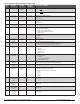
The options available in Service Menu 140 (below) are dependent on the selected
System Type, Service Menu 110.
In this operation, there is no external fossil fuel kit (dual fuel kit) installed; the thermostat
controls this function:
1. Choose the correct heat pump application in Service Menu 110, System Type.
2. Choose Outdoor Temperature Sensor (Options 3 or 5) for Control Option in Service
Menu 170, Remote Sensor.
3. Go to Service Menu 140, Auxiliary Heat, and choose “1.”
4. Choose an appropriate temperature balance point in Service Menu 180, Heat Pump
Compressor Lockout.
Operation in Heat Mode Above Balance Point (Outdoor Temperature)
When the outdoor temperature is above the selected balance point temperature (Service
Menu 180), only the compressor operates and the fan (G Terminal) energizes when the
thermostat calls for heat.
Operation in Heat Mode Below Balance Point (Outdoor Temperature)
When the outdoor temperature is below the selected balance point temperature (Service
Menu 180), only the Fossil Fuel (auxiliary heat) operates and the fan (G Terminal) does not
energize when the thermostat calls for heat.
If Service Menu 140 is set to “1” (fossil fuel Auxiliary Heat), the lockout control is as
follows:
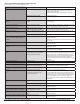
Outside Air
Temperature
40° F
Only Compressor Operates
Compressor
Lockout
Temperature
Only Auxiliary Heat Operates
1. Choose the correct heat pump application in Service Menu 110, System Type.
2. Choose Outdoor Temperature Sensor (Options 3/5) for Control Option in Service Menu
170, Remote Sensor.
3. Go to Service Menu 140, Auxiliary Heat, and choose “0.”
4. Choose appropriate balance point in the Service Menu 180, Heat Pump Compressor
Lockout.
5. Choose Auxiliary Lockout Temperature in Service Menu 190, Heat Pump Auxiliary
Lockout.
Operation
When the outdoor temperature is:
• Below the Heat Pump Compressor Lockout temperature, only the Auxiliary Heat
operates.
• Above the Heat Pump Auxiliary Lockout Temperature, only the Compressor
operates.
• Between the two temperatures, both the Compressor and Auxiliary Heat operate.
If Service Menu 140 is set to “0” (electric Auxiliary Heat) the lockout control is as follows:
Outside Air
Temperature
40° F
Only Compressor Operates
Auxiliary Lockout
Temperature
Both Compressor & Auxiliary Heat
Operate
Compressor Lockout
Temperature
20° F
Only Auxiliary Heat Operates
Performance PRO is a trademark, and PECO is a registered trademark of PECO, Inc. The PECO logo is a trademark or servicemark of PECO, Inc.
Figure 27.
Wire PECO Remote
Outdoor Sensor to
Performance PRO
wallplate, Terminal S3, SC.
Terminal S3
Terminal SC
wiring passage
Figure 28.
Service Menu
170 allows the
user to enable
the Outdoor
Remote Zone
Sensor.