
Install Instructions

© COPYRIGHT 2010 PECO, INC. ALL RIGHTS RESERVED. P/N 70478 3220-2267 REV 00
11
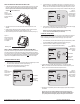
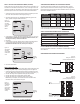
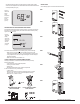
If the Indoor Remote Zone Sensor is working properly, the primary display (center)
shows the correct temperature taken at the location where Indoor Remote Zone Sensor
is currently installed (see Fig. 25).
If the thermostat Home Display appears as follows (see Fig. 26), then the Indoor Remote
Zone Sensor is not connected properly. Two dashes and the Service Indicator (wrench)
appear as the error message.
If the Indoor Remote Zone Sensor is not connected properly, check the following:
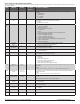
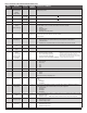
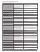
• Make sure sensor is wired properly and connected to terminals S1 and SC
on the thermostat wallplate (see Table 1, Terminal Designations & System Types).
• If using multiple sensors, make sure wiring follows diagrams in Sensor Wiring for
Temperature Averaging.
• Make sure to select “01” in Service Menu 170.
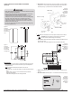
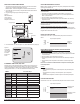
Following are instructions on the PECO Outdoor Remote Sensor (P/N 70327).
Mount the sensor where:
• It can measure true outdoor ambient temperature
• There is good air and circulation
• Surface is at
• Wire distance between the sensors cannot be tampered with
Do not mount the sensor in any of the following:
• In direct sunlight
• Where hot or cold air blows on the sensor. Discharge line from an outdoor
compressor unit, vent, or fan causes inaccurate temperature readings
• Where snow, ice, or debris can cover it
Use the following steps to mount the Outdoor Remote Sensor.
▲
Figure 25.
Thermostat
Display
shows
temperature
from Zone
Sensor
if working
properly.
Figure 26.
Thermostat
Display
shows Zone
Sensor error
message if
Sensor is
not working
properly.