
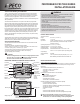
Install Instructions

© COPYRIGHT 2010 PECO, INC. ALL RIGHTS RESERVED. P/N 70478 3220-2267 REV 00
10
1. Choose a location on an interior wall near the air return grille,
about ve feet above oor level, where air circulation is good and temperature is
average for the zone.
mounting the Indoor Remote Zone Sensor in areas such as:
• Behind doors
• On outside walls, or any walls with unheated or uncooled areas behind the zone
sensor
• In direct sunlight, or near any source of radiant heat that could affect the
temperature measurements
• In line with the discharge air from the unit being controlled.
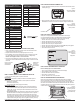
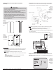
Remove Zone Sensor cover from the subbase, and mount subbase
on the wall or in a 2’ X 4” device box. Route the wires through the wire access hole in
the subbase (see Fig. 22). Seal the hole in the wall behind the subbase.
1. Run wires between the unit control panel and the Zone Sensor subbase.
2. Connect the wiring to the terminals at the thermostat wallplate (S1 and
SC) See Fig. 23, below.
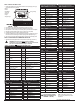
Note: See Table 1 for terminal designations for the Indoor Remote Zone Sensor.
3. Place Zone Sensor cover back on the subbase, and snap it securely
into place.
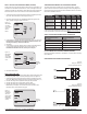
4. Select option “01” to enable the Indoor Sensor (see Fig.24).
▲
: Keep wires separate and routed away from any source of
noise such as motors, uorescent lights, and other wiring.
Figure 24.
Service Menu
170 allows the
user to enable
the Indoor
Remote Zone
Sensor.
Figure 22.
Mounting the
SP155-017
Indoor Remote
Zone Sensor.
Device box mounting
Wall mounting
Terminal S1
Terminal SC
Figure 23.
Wiring terminal
designations for
SP155-017
Indoor Remote
Zone Sensor.
• READ THESE INSTRUCTIONS CAREFULLY BEFORE ATTEMPTING TO INSTALL,
OPERATE, OR SERVICE THIS SENSOR.
• Failure to observe safety information and comply with instructions could result in
PERSONAL INJURY, DEATH AND/OR PROPERTY DAMAGE.
• To avoid electrical shock or damage to equipment, disconnect power before
installing and use only wiring with insulation rated for full sensor operating voltage.
• This product, when installed, will be part of an engineered system whose
speci cations and performance characteristics are not designed or controlled
by PECO. Review applications and national and local codes to assure that the
installation will be functional and safe.
• Do not run low-voltage control wiring in the same conduit with high-voltage wiring.
• Use in indoor applications only.
▲
Figure 20.
SP155-017
Indoor Remote
Zone Sensor,
front and side
view.
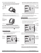
Figure 21.
SP155-017
Indoor Remote
Zone Sensor,
back view with
mounting holes.