
Install Instructions

© COPYRIGHT 2020 PECO, INC. ALL RIGHTS RESERVED. P/N 73676 3220-2372 REV 04
7
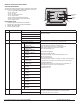
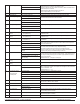
520 Default Display Icons 0- Time, Temp, SP (Default) Icons that will be displayed in the default state.
NOTE: Setpoint will not be displayed if T8168 System Mode is OFF.
1- Time, Temp
2- Time
3- Temp
4- None
5 - Set Point Only
530 Revision Displays Current Revision Information
540 Factory Default Reset 0- Disable (Default) When enable is selected he device will return to factory default settings.
1- Enable
600 Cooling System Output
Test
0- Disable (Default) Cool Operation is enabled and the associated output based on Service Menu 110. The
output is activated for 10 minutes. The ON/OFF or 0-10 VDC Fan output will automatically
turn on.
1- Stage 1 Cooling/Y1 (TWF)
2 – Stage 2 Cooling/Y2 (TWF)
610 Heating System Output
Test
0- Disable (Default) Heat Operation is enabled and the associated output based on Service Menu 110. The
output is activated for 10 minutes. The ON/OFF or 0-10 VDC Fan output will automatically
turn on.
1- Stage 1 Heating/W1 (TWF)
2 – Stage 2 Heating/W2 (TWF)
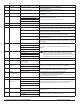
620 Fan System Output Test 0- Disable (Default) If enabled is selected it will activate Based On Service Menu 110. The output will be
enabled for 10 minutes. If a different menu is selected the output will be disabled. Wheth-
er the fan output is a triac or a 0-10VDC/4-20mA is determined by Service Menu 112
1- Enable G Fan Output/GD Low
2 – Enable Y2 Fan Output/GD Med Cool
3 - Enable G1 Fan Output/GD Hi Cool
4 – Enable GD Med Heat
5 – Enable GD High Heat
In case of difculty, try one of the following suggestions below.
Symptom Potential Cause(s) Solution
If display screen is blank • Thermostat is not being powered • Check to assure proper wiring of power to (24 VAC-1) and (24 VAC-2) .
• Check power to verify that there is 24 VAC available.
• Default Display is set to “4” (None) • Check Service Menu 520.
If keys do not allow manual entry • Keypad Lockout may be enabled • Access Service Menu 340. Within this menu, select option “0” to assure
there is no keypad lockout (so manual entry is enabled).
Service Menu does not display • PIN access is enabled
• Buttons were not pressed simultaneously
• Access requires the three digit code set by the installer.
• Wait for unit to return to default display and retry.
Err In Clock Dispay • Indicates a service fault input • Indicates service is required.
Door in Clock Display • Door or window is open • Close door and /or window to clear fault.
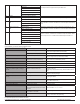
Fdd in Clock Display • Indicate an economizer or other system fault • Indicates service is required.
If no heating or cooling is running, but there is a call
for heat or cool (Heat/Cool appears on display) in
Auto mode
• Heating or cooling equipment is not operating
• Minimum off time has not been met
• Check Service Menu 110 to assure that the correct option is selected to
match the system type.
• Check wiring, using output tests to verify (see Service Menus 600, 610,
620).
If heating or cooling system doesn’t respond • System type selection is incorrect • Check Service Menus 110 and 120 to assure that the correct option is
selected to match the system type.
If heating and cooling equipment are running at the
same time
• System type selection is incorrect • Check Service Menu 110 to assure that the correct option to match the
system type is selected.
• Verify wiring connections • Separate the heating and cooling wires, using output tests to verify (see
Service Menus 600, 610, 620).
If Demand Indicator light is red • Heating is occurring • No action is required.
If Demand Indicator light is green • Cooling system is running • No action is required.
Fan outputs turned off after 3-minutes • Pipe sensor is connected and water
temperarture between hot water and cold water
set points
• Building Boiler or Chillers may be turned off.
• See Service Menus 171, 172, 173 & 174
Menu Item Not available • Some service menus are disabled when not in
use or feature is not available.
• Verify system type selection and feature selection is correct.
Red LED is Flashing and code is in clock location • Fault is present on SC and S1 input • Check SM175 for code
• If using a remote sensor, verify probe wiring.
Visit: pecocontrolsystems.com for additional information.
TROUBLESHOOTING & FREQUENTLY ASKED QUESTIONS