
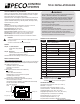
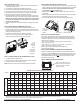
Install Instructions

© COPYRIGHT 2020 PECO, INC. ALL RIGHTS RESERVED. P/N 73676 3220-2372 REV 04
5
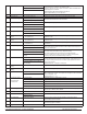
112 System Fan Type 0 = On/Off Fan (Default) 0: Uses available fan speeds per Service Menu 110
1: Uses GD output for 0-10 VDC fan. User selection of speed.
HI Speed is set at SM 125-126,LO speed is set at SM 127, MED is set between HI-LO*.
2: Uses GD output for 0-10 VDC fan.
Modulates between Min and Max selections in SM 125-127*.
*Damper Output Available (G1) and runs per SM 111
1 = 0–10VDC FAN Hi-MED-LO Fan
2 = Proportional 0-10VDC Fan
113 0-10 VDC Fan Buffer 0 to 3 Minutes, 30 sec Increments (Default 1) Sets the time delay between fan speeds when SM 112=1
114 Valve Stoke Time 30 Sec To 5 Min (Default 120) Set the amount of time for a TWF valve to go from fully closed to fully Open.
120 Fan Control (Heating) 0 – OFF for Heating (Gas/Oil Heat) 0: The thermostat will not activate the fan with a heating demand.
1: The thermostat will activate the fan with heat demand.
1= Electric Furnace (DEFAULT)
122 YD Output Configuration 0 = 4 – 20mA Configures digital cooling output for 0-10VDC or 4-20mA DC
1 = 0 – 10 Volts (DEFAULT)
123
WD Output Configuration 0 = 4 – 20mA Configures digital heating output for 0-10VDC or 4-20mA DC
1 = 0 – 10 Volts (DEFAULT)
124 GD Output Configuration 0 = 4 – 20ma Configures digital fan output for 0-10VDC or 4-20mA DC
1 = 0 – 10 Volts (DEFAULT)
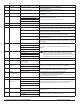
125 GD Max Voltage, Heating
Demand
6 – 10 VDC (Default: 8)
12 – 20 mA (Default: 20)
Depending on SM 124 setting, sets Fan HI speed voltage or current (mA) at terminal GD
with demand for Heat.
126 GD Max Voltage, Cooling
Demand
6 – 10 VDC (Default: 10)
12 – 20 mA (Default: 20)
Depending on SM 124 setting, sets Fan HI speed voltage or current (mA) at terminal GD
with demand for Cool.
127 GD Min Voltage 0 – 6 VDC (Default: 2)
4 – 12 mA (Default: 4)
Depending on SM 124 setting, sets Fan LO speed voltage or current (mA) at terminal GD
with no demand.
135 W1 Output Configuration 0 - NC: Normally Closed Operation (Default) Reverses the ON/OFF operation for W1. NC operation powers on with a demand. NO
opreation powers off with a demand and will be on with no demand unless main power is
removed from the thermostat.
1 - NO: Normally Open Operation
170 S1 Remote Sensor Input 0= No Remote Sensors (Default) 0: Remote temperature sensing is disabled.
1: The T8168 uses the remote sensor only for temperature sensing.
2: The T8168 averages the local and remote sensor for temperature sensing.
When using a remote sensor an open or short will turn off outputs and display either
2Ero(open) or 2Erc (closed). Fault detection settings are not used.
1= Remote Indoor Sensor Connected
2 = Remote Sensor Connected And Sensor
Averaging
171 S2 Pipe Sensor 0 – Disabled (Default) Enables fan coil pipe sensor operation. Connect a PECO pipe sensor or dry switch closure
for change over from Summer (cold water) to Winter (hot water). 2-pipe operation uses the
Cool 1 output for heating and cooling. Heat 1 is disabled. 4-pipe operation allows heat 1 in
summer mode of operation.
Available when SM 110 = 1 through 5 or 14 through 16
1 – Two Pipe Operation
2 – Four Pipe Operation (use for 2-pipe with
electric heat relay)
172 Pipe Sensor Threshold for
Cooling
50F to 72F (Default 60F) Changes to Cool when pipe temp is below threshold. Available when SM 171 = 1 or 2
173 Pipe Sensor Threshold for
Heating
75F to 90F (Default 80F) Changes to Heat when pipe temp is above threshold. Available when SM 171 = 1 or 2
174 Pipe Sensor Purge 0 = Time (Default) TEMP: Purge continues until a non-ambiguous condition is sensed.
TIME: A 3-minute purge is started. Once complete and still ambiguous mode all thermostat
outputs are disabled for 1 hour.
Available when SM 171 = 1 or 2
1 = Temp
175 Fault Detection/ Setback
(requires SM170=0)
No remote probe
0 = Disabled (Default) When enabled connect dry switch between S1 and SC.
1 = Active On Open Displays “Door” in clock location, turn outputs OFF, blink red LED
2 = Active On Open Displays “Fdd” in clock location, outputs function normally
3 = Active On Close Displays “Err” on clock location, turn outputs OFF blink red LED
4 = Occupancy Sensor Sets thermostat to setback with a closure at SC and S1 .
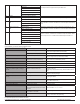
240 Number of Program Events 2 or 4 Events (DEFAULT = 2) When the T8168 is set up as programmable this sets the number of events per day.
Events are OCC1, UNOCC1, OCC2, UNOCC2
250 Clock Format 12 or 24 Hrs (Default = 12) This service menu sets the clock format.
260 F or C 0- Celsius Determines temperature displays in Fahrenheit or Celsius
1- Fahrenheit (Default)
270 Fan Off Delay Heat 0-99 Seconds (0-Default) The amount of time (in seconds) the lowest available fan speed will run after the
thermostat heating outputs are disabled
280 Fan Off Delay Cool 0-99 Seconds (0-Default) The amount of time (in seconds) the lowest available fan speed will run after the
thermostat cooling outputs are disabled
290 Range Low 50-90 F (50F- Default) The lowest selectable temperature setpoint value