
Install Instructions

© COPYRIGHT 2020 PECO, INC. ALL RIGHTS RESERVED. P/N 73676 3220-2372 REV 04
4
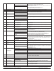
Menu Feature Options Description
100 Schedule Format 0 = Nonprogrammable (Default) Selects the schedule format. In non-programmable mode all scheduling functions are
removed from the display.
1 = Programmable
2 = 5-1-1 Schedule Mode
3 = 5-2 Schedule Mode
101 Daylight Savings 0 = Disabled (Default) When enabled daylight savings time follows the US 2007 format. (Begins second Sunday
of March at 2AM and ends on the first Sunday of November at 2AM.
1 = Enabled (2007 US Format)
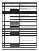
110 System Type
1
1 Stage Heat /1 Stage Cool
Fan: Single Speed
System Type Notes
• Fan can be changed from ON/OFF to 0-10 VDC Operation.
• Stage 1 operation includes Y1/ W1 and 0-10 VDC outputs YD./ WD
• System types may disable some service menu unavailablity
• TWF = Three Wire Floating (valve)
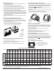
Typical System Conguations:
2-Pipe Fan Coil with Electric Heat
• Connect the Valve to Stage 1 Cool and the Heat Relay to Stage 1 Heat
• SM110=01,02,03,04,05 or 14
• SM171=02 (4-Pipe Operation)
• When using a pipe sensor, Operation of Cool Stage 1 will change. In winter, heating will
be provided from the valve (Stage 1 Cool) and Electric Heat (W1) will be disabled.
Error Detection/ Notication
• Condensate overow, door open or economizer can be set in Service Menu 175
• Connect external dry switch at S1 and SC. See wiring diagram.
0-10 VDC Fan Operation
• Change SM112= 01 or 02
2
2 Stage Heat /1 Stage Cool
Fan: Single Speed
3
1 Stage Heat /1 Stage Cool
Fan: 3-Speed
4
2 Stage Heat /1 Stage Cool
Fan: 3-Speed
5
2 Stage Heat / 2 Stage Cool
Fan: 2-Speed
6
Heat Only
Fan: Single Speed
7
Cool Only
Fan: Single Speed
8
Heat Only
Fan: 2-Speed
9
Cool Only
Fan: 2-Speed
10
Heat Only
Fan: 3-Speed
11
Cool Only
Fan: 3-Speed
12
Heat: TWF Cool: 2 Stage Cool
Fan: 2-Speed
13
Heat: TWF Cool: 1 Stage Cool
Fan: 3-Speed
14
Heat: 2 Stage Heat Cool: TWF
Fan: 2-Speed
15
Heat: TWF Cool: TWF (Default)
Fan: 2-Speed
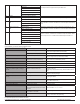
111 Damper Configuration 0 – Damper Continuous Damper output is not available when being used as a fan speed.
0: G1 output runs continuously when thermostat is not in System OFF Mode.
1: G1 output cycles with a heat or cool demand.
1 – Damper Cycled with Demand (Default)
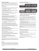
ADVANCED CONFIGURATION SERVICE MENUS
CONFIGURE SERVICE MENUS
The following Service Menus (SM) commonly require conguration. Please verify that
these are set for your specic application. Additional conguration may be required.
• SM 100 = Programmable or Nonprogrammable
• SM 110 = System Type
• SM 112 = Fan Type
• SM 135 = W1 Heat Output NO or NC
• SM 170 = Remote Sensors
• SM 240 = Number of Programmable Events per Day
• SM 395 = Override Duration for Programmable Operation
• SM 340 = Keypad Lock Out
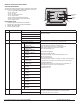
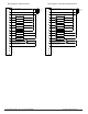
SERVICE MENU ACCESS
1. Hold lower right and lower left keys for ve seconds.
2. Press Next or Go Back button to select a Service Menu.
3. Press ▲/ ▼ to select option.
4. Press Done when complete.
Selected
Option
Service Menu
Number