
Install Instructions

© COPYRIGHT 2020 PECO, INC. ALL RIGHTS RESERVED. P/N 73676 3220-2372 REV 04
3
THERMOSTAT PROGRAMMING
This thermostat is easily changed from non-programmable to programmable
operation in Service Menu 100. See the Operating Maunal for detailed
instructions on setting up schedules. In non-programmable mode the thermostat
controls to a single setpoint with the dead band used for auto changeover from
Heat to Cool.
OUTPUT OPERATION
The T8168 uses System Types for control of 24 VAC ON-OFF fans and relays;
three wire oating and proportional 0-10 VDC fans, valves and dampers.
• ON-OFF outputs have a 1°F Differential.
• Proportional outputs use a Proportional Integral Algorithm to modulate the
position of the actuator over 2°F.
• Three Wire Floating outputs have an adjustable stroke time that is set in
Service Menu 114. The default is 2 minutes.
When using Three Wire Floation (TWF) System Types wait 3 times the value set
for Valve Stroke Time, set in SM 114, for normal operation to begin.
FAN AND DAMPER OPERATION
The T8168 offers either ON-OFF or 0-10 VDC fan operation, as follows:
ON/OFF FAN Operation (Service Menu 112 Selection 0)
The thermostat will provide up to 3 fan speeds. In this operation there is no
proportional fan output, terminal GD is disabled. Selectable fan speeds are
controlled by Service Menu 110.
0-10 VDC FAN HI-MED-LOW Operation (Service Menu 112 Selection 1)
User selection of 0-10 VDC (or 4-20mA) fan speed is as follows:
• HI – Set in SM 125 for heating and SM 126 for cooling.
• MED - Controls at the mid point between the HI and LO settings.
• LO – Set in SM 127.
A delay of fan speed transition after adjustment can be set in SM 113.
Proportional 0-10 VDC Operation (Service Menu 112 Selection 2)
The 0-10 VDC fan will range between MAX and Min Voltages (SM 125,126,127)
based on the PI algorithm, the active demand and selected limits. Display of
HI-MED-LO is suppressed. User selection is limited to FAN ON or FAN AUTO,
depending on conguration.
Damper Operation (Service Menu 111)
A damper output is available when terminal G1 is not being used as a fan speed.
Cycled vs continuous operation is determine in SM 111.
Staged Fan Operation (Service Menu 350)
Available for multi-fan and 0-10 VDC fan operation. When active, the user does
not have access to fan speed.
Programmable Fan Operation (Service Menu 500)
This feature changes the fan operation to ON (continuous) during scheduled
Occupied events. TIP: Disable Fan ON selection in SM 350 to ensure cycled
operation in unoccupied scheduled events.
Intermittent Fan Operation (Service Menus 500, 501, 502)
Provides minimum timed fan operation by cycling the fan on and off.
KEYPAD LOCK OUT
The keypad lockout function blocks access to features by hiding them from the
user’s view/selectability. Service Menu 340 has 3 levels of lock out. If a PIN is
used to enter the Service Menu, all key pad lockouts will be disabled for a period
of ve minutes.
SETBACK
An occupancy sensor can be used between S1 & SC terminals to change the
thermostat control points to Setback Low (SM 310) and Setback High (SM 320).
A contact closure is used to signal a Setback requirement. In Setback the fan will
cycle on at the lowest available speed. This feature is not available when using a
remote sensor.
FAN COIL 2-PIPE/ 4-PIPE OPERATION
Service Menu 171 sets 2-pipe or 4-pipe fan coil operation.
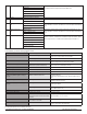
2-Pipe Operation Summer
(Cold Water or Open Input)
Winter
(Hot Water or Closed Input)
Stage 1 Cool Y1 & YD Cool Heat
Stage 1 Heat W1 & WD Disabled Disabled
• 2-pipe operation disables W1 and WD outputs. Y1 and YD are used for rst
stage of cool in summer and rst stage of heat in winter.
4-Pipe Operation Summer
(Cold Water or Open Input)
Winter
(Hot Water or Closed Input)
Stage 1 Cool Y1 & YD Cool Heat
Stage 1 Heat W1 & WD Heat Disabled
• 4-pipe operation uses both rst stage Cool (Y1 & YD) and rst stage Heat (W1
& WD) when chilled water (Summer) is available. When hot water (Winter) is
available W1 and WD outputs are disabled and Y1 and YD are used for rst
stage of heating. Second stages are available, depending on system type.
PIPE SENSOR: SEASONAL CHANGE OVER
This feature is enabled when 2-pipe or 4-pipe operation is selected in Service
Menu 171. With a pipe sensor connected to the T8168, the system will
automatically change from Summer (cold water) to Winter (hot water) operation
based on water temperature in the main piping riser. This input is looking for a
valid temperature reading when using a pipe sensor, or a contact open/close if
using an aqua-stat.
• Summer operation is enabled if the input is open or if the sensed temperature
is below the threshold selection in SM 172.
• Winter operation is enabled if the input is closed or if the sensed temperature is
above the threshold selection in SM 173.
If the water temperature sensed is between selections in SM 172 and SM 173
the water temperature is considered Ambiguous. The Y1 and YD outputs will be
turned on for 3-minutes. After the 3 minute purge cycle, the thermostat checks
again to see if the water temperature is Summer or Winter. If yes, the thermostat
will transition to normal operation. If no, the operation is base on selection at
Service Menu 174.
NOTE: If at any time the demand goes away, the thermostat will abort the purge
cycle.
SYSTEM FLUSH FOR FAN COIL VALVES
Enable a periodic opening of valve(s) to ush valves and reduce sediment buildup
using Service Menus 375, 376 and 377.
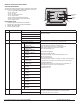
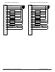
ACCESSORY SENSOR CONNECTIONS
S1 Input: connect optional remotes sensing, occupancy detection, door open or
fault notication.
• For Remote Probe use, including sensor averaging between the onboard
sensor and the remote sensor, see SM 170.
• For occupancy, door open or fault notication see SM 175
S2 Input: uses a a PECO pipe sensor or dry switch aqua-stat for use on fan coil
seasonal change over.