
Install Instructions

© COPYRIGHT 2020 PECO, INC. ALL RIGHTS RESERVED. P/N 73676 3220-2372 REV 04
2
PART I: INSTALL WALL PLATE
1. Position the wall plate on the wall with the directional arrow pointing up and
terminal blocks facing outward.
2. Pull equipment wires through the wall plate wiring passage.
3. Use a level to determine the best horizontal wall plate mounting position.
4. Mark positions of screw holes (two) with a pencil and remove wall plate.
5. Drill holes at pencil-marked locations (3/16” for drywall, 7/32” for plaster).
6. Insert the wall anchors in the holes, tapping them into place.
7. Mount the wall plate onto the wall and insert screws through mounting holes.
Assure that all loose wires come through the center opening of the wall plate.
Note: Do not over-tighten screws or use excessive force. This can cause
the wall plate to warp and may cause intermittent connections between
the base and the thermostat.
8. Cap off any unused wires and terminate properly according to local building
codes.
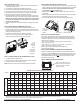
PART II: ATTACH WIRES TO THERMOSTAT WALL PLATE
1. Select the terminal designations that correspond to the system type.
2. Using a small athead screwdriver, loosen the screws on the terminal blocks,
Strip the insulation of each wire at a proper length (about 1/4” or 64 cm) and
insert wires into the terminal blocks.
3. Assure that no uninsulated wires are exposed: Cap off and
place a wire-nut on any unused wires. Assure that the attached
wires t into the cavity on the back side of the thermostat.
PART III: CONNECT POWER TO THE THERMOSTAT WALL PLATE
1. The T8168 operates on 24VAC power.
2. Connect the common side of the transformer to the “24 VAC-1” terminal.
3. Connect power side to the “24 VAC-2” terminal.
NOTE: Wait at least one hour for the displayed temperature to stabalize.
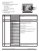
PART IV: MOUNT THE T8168 ONTO THE WALL PLATE
1. Position the thermostat slightly above the mounted wall plate, then secure the
hooks on the back side of the thermostat to the hinge pockets on the wall plate.
Note: The top back side of the thermostat should slip into the hinge
pockets easily. Do not use excessive force.
2. Align the pins on the back side of the thermostat with the terminal blocks on
the wall plate.
3. Gently bring down the thermostat onto the wall plate so the pins on the back of
the thermostat t into the terminal blocks on the wall plate.
4. Attach the retaining screw to the underside of the thermostat as shown.
PART V: SET CLOCK, MONTH, AND DAY
When power is rst applied to the thermostat, it will activate the clock display.
It is recommended that time and day are entered before performing advanced
conguration. Setting the clock can also be accessed by selecting MORE then
CLOCK. Set clock as follows:
• ▲/ ▼= Arrows set selection. Note: The ashing option is the default selection.
• NEXT = Advances to next menu.
• Menu selections are: 12 to 24 hour format - Hour - Minutes - Year - Month - Day
• DONE = Press Done when operation is complete.
NOTE: Display of Clock is not available when congured for
non-programmable operation.
PART VI: VERIFY THERMOSTAT OPERATION WITH SYSTEM TESTS
System test verication is highly recommended to verify thermostat operation.
For all system tests, press Next to continue to the following system test, or next
available Service Menu. Press Done only if nished performing all system tests.
Pressing Done exits the Service Menus and turns off all active outputs. See
Service Menus: 600, 610, 620.
PART VII: REMOVE BATTERY INSULATOR TAB
Remove Insulator Tab after power is
applied.This tab protects onboard bat-
tery prior to installation. This battery
backups up the clock.
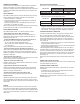
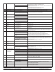
SM110 = 1 2 3 4 5 6 7 8 9 10 11 12 13 14 15 16
1 Heat
1 Cool
1 Fan
2 Heat
1 Cool
1 Fan
1 Heat
1 Cool
3 Fan
2 Heat
1 Cool
3 Fan
2 Heat
2 Cool
2 Fan
Heat
Only
1 Fan
Cool
Only
1 Fan
Heat
Only
2 Fan
Cool
Only
2 Fan
Heat
Only
3 Fan
Cool
Only
3 Fan
Heat TWF
1 Cool
2 Fan
TWF Heat
1 Cool
3 Fan
TWF Cool
1 Heat
2 Fan
TWF Heat
TWF Cool
2 Fan
0-10
VDC
Only
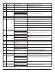
ON-OFF Outputs
Y1 Cool 1 Cool 1 Cool 1 Cool 1 Cool 1 - Cool 1 - Cool 1 - Cool 1 Cool 1 Cool 1 Cool Open Cool Open -
W1 Heat 1 Heat 1 Heat 1 Heat 1 Heat 1 Heat 1 - Heat 1 - Heat 1 -
Heat
Open
Heat
Open
Heat 1 Heat Open -
Y2 - - FAN MED FAN MED COOL 2 - Cool 2 - Cool 2 FAN MED FAN MED Cool2 FAN MED
Cool
Close
Cool Close -
W2 - Heat 2 - Heat 2 Heat 2 Heat 2 - Heat 2 - Heat 2 -
Heat
Close
Heat
Close
Heat 2 Heat Close -
G FAN FAN FAN HI FAN HI FAN HI FAN FAN FAN HI FAN HI FAN HI FAN HI FAN HI FAN HI FAN HI FAN HI -
G1 Damper Damper FAN LO FAN LO FAN LO Damper Damper FAN LO FAN LO FAN LO FAN LO FAN LO FAN LO FAN LO FAN LO Damper
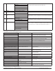
0-10
VDC
YD Cool 1 Cool 1 Cool 1 Cool 1 Cool 1 - Cool 1 - Cool 1 - Cool 1 Cool 1 Cool 1 Cool 1 Cool 1 Cool 1
WD Heat 1 Heat 1 Heat 1 Heat 1 Heat 1 Heat 1 - Heat 1 - Heat 1 - Heat 1 Heat 1 Heat 1 Heat 1 Heat 1
SYSTEM TYPE: Service Menu 110 Output Conguration
• When System Fan Type (SM112) is set to 1 or 2 (0-10 VDC operation), the GD output is the only fan oputput and G1 provides Damper operation.
• When Fan Coil 2-Pipe operation is selected the W1 and WD outputs will be disabled. See SM 171.
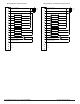
Insert
wires into
appropriate
terminal
blocks.
Enlarged area
shows wire
insertion point at
terminal block.
Secure hooks
on back side of
thermostat to
wallplate.
Retaining screw