
Install Instructions

© COPYRIGHT 2010 PECO, INC. ALL RIGHTS RESERVED. P/N 69563 3220-2181 REV 00
1
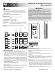
SDP155-008 Digital Display
Zone Sensor
CAUTION
• Hazardous Voltage! Disconnect all electrical power, including remote disconnects
before servicing. Follow proper lockout/tagout procedures to ensure the power cannot
be inadvertently energized. Failure to disconnect power before servicing could result in
death or serious injury.
• Use copper wire only, insulate or wire nut all unused leads.
• Care should be used to avoid electrostatic discharge to the thermostat.
SPECIFICATIONS
Input Power: NEC Class 2, 18-32 VAC 50/60, 24 VAC nominal
1 VA max.
Communication Jack: Accessible through bottom of cover
Operating Temperature: 32 to 120°F (-0° to 49°C)
Shipping Temperature: -4° to 130°F (-20° to 54°C)
Operating Humidity: 5 to 95% non-condensing
Physical Dimensions: 2.8 x 4.5 x 1.2 (71.1 x 114.3 X 27.8 mm) including button heights
Mounting: Vertically ush mount or mount on standard (50.8 X 101.6mm)
2x4 in. (71.1 x 114.3 x 27.8 mm) device
Compatibility: Compatible with TRANE
™
unit control modules (UCM)
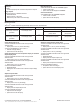
WIRING DIAGRAM
Digital Display Zone Sensor Wiring Terminals
MP501 AH540
VAV 4.2 ZN511 AH541
VV550 ZN517
VV551 ZN521
TB1 TB1 AC Power
1
24V AC*
TB1-1
24V
24V 24VAC
2
24VGND*
TB1-2
GND
GND 24VAC
GND
TB2 TB3
ZONE
SENSOR INPUTS
1 ZONE
TEMP
TB3-1
ZONE
ZN IN 1
2
SENSOR
GND
TB3-2
GND
GND GND
3
SETPOINT
TB3-3
SET
SET IN 2
4
TB3 TB2 COMM 5 COMM 5
1
COMM +
TB2-1 + A A
2 COMM - TB2-2 - B B
PRE-INSTALLATION NOTES
1. All wiring must be in accordance with NEC and local building codes.
2. Do not run low-voltage wiring in the same conduit with high-voltage power wiring.
3. Sharing the 24V Class 2-power source from the UCM is the preferred practice and
simplies installation. See wiring diagram above and wiring requirements under item 4 at
right. Use caution to be sure 24V and GND are connected to the proper terminals when
connecting to the UCM.
4. If a separate 24V Class 2 power source is used to power the Digital Zone Sensor,
terminals TB1-2 (24V GND) and TB2-2(Sensor GND) must be jumpered together at the
sensor for the sensor to operate. However, the usage of a transformer, with the supply
voltage greater than 150V to ground as the separate 24V Class 2 power source is not
recommended because its output should be grounded to building ground (following NEC
requirements for Class 2 devices.) This additional grounding can affect the operation and/
or damage the Digital Zone Sensor.
5. The sensor display will not be enabled with 24V connection only. Sensor signal wiring to
the UCM must be connected for the display to function.
6. Sensor must be connected to a UCM and powered up for at least 1 hour to achieve
maximum accuracy.
7. “Sensor setpoint” output cannot be veried with an ohm meter. Connection to a UCM is
necessary to verify operation.
8. Plug holes through the wall behind the sensor to prevent undesirable airow.
INSTALLATION INSTRUCTIONS
1. Choose Mounting Location. Choose a location on an interior wall near the return
air grille about ve feet above the oor. Air should circulate freely and be of average
temperature for the zone. Avoid such areas as:
• Behind doors
• On outside walls or facing uncontrolled areas
• in direct sunlight or near sources or radiant heat that may affect the temperature
measurement
• in-line with discharge air from unit being controlled.
2. Remove cover. Remove zone sensor cover by easing the tip of a small screwdriver into
the top rear center slot closest to the wall. Gently move the top of the screwdriver towards
you. Excessive force is not recommended fro cover removal.
3. Mount base. Remove zone sensor cover from base and mount on wall or 2X4 device
box.
4. Connect Wires. Connect wires as shown in the wiring diagram. For wire lengths
less than 75 feet, an 18 gage, 5 or 6 conductor cable may be used. For wire lengths
greater than 75 feet, use 18 gage, 2-conductor cable for the power wiring (TB1), and
18 gage, 3 conductor cable for signal wiring (TB2). Avoid routing wires near sources of
electrical noise such as motors, uorescent lights, LAN wiring, etc. In some high-noise
environments, signal wires may require shielding. The communication jack should be
wired with the cable appropriate for the system being installed.
5. Replace Cover. Place zone sensor cover back on the base and snap securely into place.
▲
!
2.8
4.5
1.1
1.0
.34 REF
CANCEL
ON
*Note: Wiring backwards will result in product failure.
WARNING
• READ THESE INSTRUCTIONS CAREFULLY BEFORE ATTEMPTING TO INSTALL,
OPERATE OR SERVICE THIS THERMOSTAT.
• Failure to observe safety information and comply with instructions could result in
PERSONAL INJURY, DEATH AND/OR PROPERTY DAMAGE.
• To avoid electrical shock or damage to equipment, disconnect power before installing or
servicing and use only wiring with insulation rated for full thermostat operating voltage.
• To avoid potential re and/or explosion do not use in potentially ammable or explosive
atmospheres.
• Retain these instructions for future reference. This product, when installed, will be part
of an engineered system whose specications and performance characteristics are not
designed or controlled by PECO. You must review your application and national and
local codes to assure that your installation will be functional and safe.
▲
!