
Accessory List
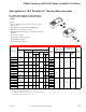


MA40-704x Series, MA41-707x Series, and MA41-715x Series
82
© Copyright 2006 TAC. All Rights Reserved. F-27382-1
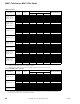
Typical Applications
MA41-7153
MA41-7073
MA41-7153-502
MA41-7073-502
MA41-7150
MA41-7151
MA41-7070
MA41-7071
MA41-7150-502
MA41-7151-502
MA41-7070-502
MA41-7071-502
24 Vac
2
2
Red
Black
Common
Hot (+DC)
1
Line
Volts
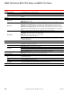
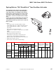
1 Provide overload protection and disconnect as required.
2 Actuators may be wired in parallel. All actuator black
wires are connected to the transformer common and all
red wires are connected to the hot lead. Power
consumption must be observed.
3 For end position indication, interlock control, fan startup,
etc., MA41-7153-502 and MA41-7073-502 models
incorporate two built-in auxiliary switches.
1
Common
Hot
120 Vac or
230 Vac
SPST Control Contact
Green/Yellow
Green/Yellow
Wire No. 1
Wire No. 2
L1 N
L2 H
24 Vac Transformer
or 22-30 Vdc
Orange/White
Violet/White
Yellow/White
N.C.
N.O.
3
Orange
Violet
Yellow
N.C.
N.O.
Aux Switch 1
25 to 85˚
Adjustable
Aux Switch 2
5˚ Fixed
Com
Com
Aux Switches
MA41-7xxx-502
Optional Auxiliary
Switches
Voltage Wire 1 Wire 2
120 Vac White Black
230 Vac Light Blue Brown
Figure 1 Typical Wiring Diagram for 24, 120, or 240 Vac Basic and Double Auxiliary Switch Models.
MA40-7040
MA40-7041
MA40-7040-501
MA40-7041-501
120 Vac, or
230 Vac
Wire No. 1
Wire No. 2
Hot
2
2
Wire No. 2
Wire No. 1
Neutral
Hot
L1 N
L2 H
L1 N
L2 H
1
1
3
Orange
Violet
Yellow
N.C.
COM.
N.O.
Auxiliary Switch 1
120 Vac, or
230 Vac
Green/Yellow
Green/Yellow
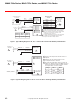
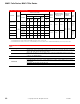
1 Provide overload protection and disconnect as
required.
2 Actuators may be wired in parallel. Power
consumption must be observed.
3 For end position indication, interlock control, fan
startup, etc., MA41-715x-502 and MA41-707x-502
models incorporate two built-in auxiliary switches.
See Specifications section for details.
Voltage Wire 1 Wire 2
120 Vac White Black
230 Vac Light Blue Brown
0 to 1 Scale
Adjustable
Neutral
Figure 2 Typical Wiring Diagram for 120 Vac or 230 Vac Basic and Single Auxiliary Switch Models.