
Accessory List
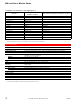
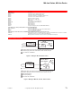


HC-101 Series, HC-201
F-27382-1 © Copyright 2006 TAC. All Rights Reserved. 69
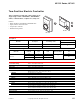
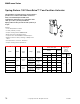
Two-Position Electric Controller
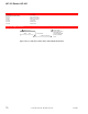
Model Chart
Specifications
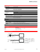
These controllers provide low or line voltage on-off
single stage control of humidifiers, dehumidifiers,
valves, solenoid valves, compressors, relays, etc.
Features:
• SPDT switching for humidification/dehumidification.
• Agency listed room and duct units.
• Long life nylon elements.
• Standard locking feature.
Description.
Model No. Description Scale Range % RH
Differential % RH
Switch
HC-101 Room 10 to 90
5
HC-201 Duct 15 to 95
Maximum Electrical Ratings.
Model No.
AC Volt
50/60 Hz
FLA LRA Resistive Amps
Pilot Duty
VA
HC-101
HC-201
24 — —
8
60
240 3.6 21.6
345
120 7.2 43.2
Control dial settings Refer to Description Model Chart.
Humidity sensing element Nylon ribbon.
Differential Refer to Description Model Chart.
Environment
Ambient temperature limits
Operating: 40 to 125°F (4 to 52°C).
Shipping and Storage: -40 to 140°F (-40 to 60°C).
Humidity 5 to 95% RH non-condensing.
Locations NEMA Type 1.
Electrical Switch One snap-acting SPDT.
Ratings Refer to Maximum Electrical Ratings Model Chart.
Connections Color coded wire leads.
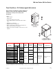
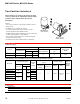
Mounting
HC-101 Flush or surface switch boxes or, for 24 V only, directly to wall.
HC-201 In any position on the outside surface of return air duct.
Dimensions
HC-101: 4-3/8 H x 2-7/8 W x 1-5/8 D in. (111 x 73 x 41 mm).
HC-201: 4-3/4 H x 6-1/2 W x 3-1/2 D in. (121 x 165 x 89 mm).
Cover HC-1xx: Plastic. HC-2xx: Metal. CH21-1: Metal.
Agency Listings HC-101 and HC-201: UL. HC2-101 and HC-201: CSA.
General Instructions HC-101: Refer to F-15143. HC-201: Refer to F-24213.
C
-
101
e
ries,
C-201
2
0
4
060
8
0
HC-101
H
C
-2
01