
Accessory List
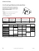


CP-9301-xxx Series, CP-9302-xxx Series
68
© Copyright 2006 TAC. All Rights Reserved. F-27382-1
Typical Applications
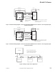
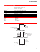
Figure 1 Service Application Wiring Diagram.
Blue
CP-9301 or
CP-9302
Actuator Drive
Yellow
MP-3xx, MP-4xx, MP-21xx,
or MP-97xx Series Actuator
To
Controller
100
Ohm
Slidewire
Wire Nuts
Actuator
Terminals
7
Brown
4
8
3
2
L1 (H)
L2 (G)
Limit
Switches
Field Winding
From
Power
Source
Yellow/Black
Blue/Black
3
4 6 7
7
5
Red/Black
3
Brown/Black
3
Brown/White
3
1 2
Shading Windings
X
8
Purge Override
(Input Signal
Override)
Violet/White
Violet
Purge Input
(Override Input)
Purge +
(Override +)
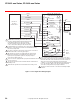
2 As diagrammed, increasing input causes CW actuator rotation. All
references to the direction of rotation are determined by facing
the actuator output shaft.
3 The wires to terminals 7 and 8, and 2 and 3, may be reversed for
CCW rotation with an increasing input signal.
4 MP-xxxx-xxx-x-2 models are equipped with an external green
jumper from terminal X to the terminal block mounting screw
(ground). If the application requires it, this jumper may be
removed for isolation purposes.
5 24 Vac models are equipped with a jumper from terminal G to the
case ground screw.
6 The green/yellow wire must be installed under the terminal block
mounting screw.
7 Shield must be grounded to the terminal block mounting screw.
1 Caution: Before installing the actuator drive onto
actuators equipped with an internal transformer, the
red and blue leads must be disconnected from
actuator terminals 7 and 8, and taped off. Failure
to do so will result in damage to the actuator drive.
8 Purge override (input signal override) is available on CP-9302
only. A dry contact closure from the override input (violet/white)
lead to the blue lead of the actuator drive forces the actuator to
drive to the end of travel, independent of the input signal
conditions. Connecting the violet/white and violet leads together
forces the actuator to drive to the opposite (high input signal)
end of travel, independent of input signal conditions.
This wire should be removed on CP-9302 when driving multiple
actuators.
Drive Input
Common
6
Green/Yellow
Green
9
9