
Accessory List
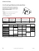


CP-8391-91x Series
F-27382-1 © Copyright 2006 TAC. All Rights Reserved. 61
Specifications
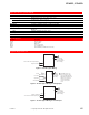
Typical Applications
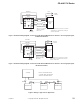
Figure 1 Typical CP-8391-91x Used On Actuator.
Inputs
Control signal
Range: 4 to 20 mAdc, non-adjustable.
Span: 16 mAdc.
Start point: 4 mAdc.
Impedance: 250 Ω.
Grounding: Either input wire can be grounded and will not cause damage, provided the electric gear
train actuator is ungrounded.
Hysteresis: 6 to 9% of 16 mAdc span, nonadjustable. (Hysteresis is the difference in input signal
between that signal which will drive the actuator shaft one way and the signal which will drive it the
other way.)
Power requirements Refer to Model Chart.
Power Consumption Refer to Model Chart.
Linearity 0.15% of 16 mAdc span.
Outputs To control windings of gear train actuators, see “Typical Actuators.”
Connections Color coded pigtail leads.
Mounting Directly to an actuator. The upright position is preferred, but other positions are acceptable.
Case Bakelite.
Environment
Ambient temperature limits
Shipping and storage: -40 to 140° F (-40 to 60°C).
Operating: -40 to 140° F (-40 to 60°C).
Humidity 5 to 95% RH, non-condensing.
Vibration 1G maximum in any plane.
Dimensions 4 H x 4 W x 3-1/4 D in.(102 x 102 x 83 mm).
Agency Listing
UL 873
Underwriters Laboratories (File #E9429 Category Temperature-Indicating and Regulating
Equipment.
CSA Canadian Standards C22.2 No. 24-93.
General Instructions Refer to F-22453.
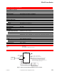
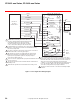
Blue (-)
CP-8391-91x
Drive
Orange (+)
(-)
MP-3xx, MP-4xx, MP-21xx
Series Actuator
4-20 mAdc Signal
(Grounded or
Ungrounded Controller)
100
Ohm
Slidewire
Wire Nuts
Actuator
Terminals
7
(+)
Brown/White
Brown
Brown/Black
Red/Black
Blue/Black
4
8
3
2
L1 (H)
L2 (G)
Limit
Switches
Remove
Green Jumper
Field Winding
Power
Yellow/Black
Black
x
Part Number Vac
Cp-8391-910
CP-8391-913
120
24
Color
White
Black/Blue
1
2
3
3
3
3
3
1 2
For actuator with internal
transformers. Disconnect red
and blue leads from actuator
terminals 7 and 8 and tape
off.
Diagram Shown; Increasing
input causes CCW actuator
rotation. All references to the
direction of rotation are
determined by looking at the
actuator output shaft.
For CW rotation with an
increasing input signal,
reverse the wires.
to terminals 7 & 8 and 2 & 3.