
Accessory List
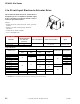


CP-8391-716 Series
F-27382-1 © Copyright 2006 TAC. All Rights Reserved. 59
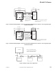
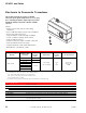
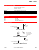
Figure 2 Installation Wiring Diagram, CP-8391-716 to MP-98xx and MP-99xx Series Actuators, Increasing Input Signal,
CCW Actuator Rotation.
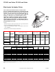
Figure 3 Installation Wiring Diagram, CP-8391-716 to MP-98xx and MP-99xx Series Actuators, Increasing Input Signal,
CW Actuator Rotation.
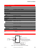
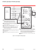
Figure 4 Wiring for Typical Series Application.
Actuator
4
5
6
7
3
8
2L1
1
X
L2
Black-White (240 Vac
(Wire to L1 on 240 Vac
Actuators and Tape
Blue Lead.)
AC Supply
Brown
White-Blue
Black-Blue
Red +
Black -
To mAdc
Controller
Note: All references to direction of actuator
shaft rotation are determined by looking at
actuator output shaft.
Orange
Blue (120 Vac)
Violet (COM)
CP-8391-716
Actuator
Drive
Yellow
Red-Yellow
Actuator
4
5
6
7
3
8
2L1
1
X
L2
Black-White (240 Vac
(Wire to L1 on 240 Vac
Actuators and Tape
Blue Lead.)
AC Supply
Brown
White-Blue
Black-Blue
Red +
Black -
To mAdc
Controller
Note: All references to direction of actuator
shaft rotation are determined by looking at
actuator output shaft.
Orange
Blue (120 Vac)
Violet (COM)
CP-8391-716
Actuator
Drive
Yellow
Red-Yellow
CP-8391-716
CP-8391-716
CP-8391-716
Note: A controller with 20 mA
of current output can drive three
CP-8391-716 actuator drives.
Controller
Red
Black
Red
Black Red
Blac
k
+
-
+
-
+
-
+-