
Accessory List


CP-8391-716 Series
58
© Copyright 2006 TAC. All Rights Reserved. F-27382-1
Specifications
Typical Applications
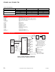
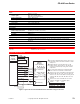
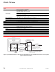
Figure 1 Typical Wiring Diagram, CP-8391-716 to MP-4xx and MP-21xx Series and MP-9750 Actuators, Increasing Input
Signal, CCW Actuator Rotation.
Inputs
Control signal
Range: 4 to 20 mAdc, non-adjustable.
Span: Adjustable 4 to 16 mAdc.
Start point: Adjustable from 2 to 16 mAdc.
Impedance: 250 Ω.
Grounding: Either input wire can be grounded and will not cause damage, provided the electric gear
train actuator is ungrounded.
Hysteresis: 3 to 5% of 16 mAdc span, nonadjustable. (Hysteresis is the difference in input signal
between that signal which will drive the actuator shaft one way and the signal which will drive it the
other way.)
Power requirements 120 or 240 Vac ±10%, fixed input signal offset ±1% maximum.
Power consumption 3.5 Va.
Linearity 0.15% of actuator rotation.
Outputs To control windings of gear train actuators, see “Typical Actuators.”
Connections Color coded pigtail leads.
Mounting Directly to an actuator. The upright position is preferred, but other positions are acceptable.
Case Bakelite.
Environment
Ambient temperature limits
Shipping and storage: -40 to 140° F (-40 to 60°C).
Operating: -13 to 140° F (-25 to 60°C).
Humidity 5 to 95% RH, non-condensing.
Vibration 1G maximum in any plane.
Dimensions 4 H x 4 W x 3-1/4 D in.(102 x 102 x 83 mm).
Agency Listing UL Recognized.
General Instructions Refer to F-21220.
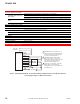
Actuator
4
5
6
7
3
8
2L1
1
X
L2
Black-White (240 Vac
(Wire to L1 on 240 Vac
Actuators and Tape
Blue Lead.)
AC Supply
(COM)
Brown
White-Blue
Black-Blue
Red-Yellow
Red +
Black -
To mAdc
Controller
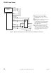
Note: All references to direction of actuator
shaft rotation are determined by looking at
actuator output shaft.
CAUTION
Actuator must not have built-in
transformer, or if a built-in
transformer is present, remove
red and blue leads from the
transformer to terminals 7 and 8
and tape off.
Orange
Blue (120 Vac)
Violet (COM)
CP-8391-716
Actuator
Drive
Yellow