
Accessory List


CP-8391-456
56
© Copyright 2006 TAC. All Rights Reserved. F-27382-1
Specifications
Typical Applications
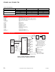
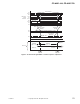
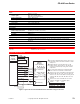
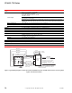
Figure 1 Typical Wiring Diagram, CP-8391-456 to MP-4xx and MP-21xx Series and MP-9750 Actuators,
Increasing Input Signal, CCW Actuator Rotation.
Electronic Actuator Drive inputs
Compatible with variable Vdc
input signal
Grounding: Either or both input wires grounded will not cause damage.
Maximum: 40 Vdc.
Isolation: Optically.
Power
Requirements: 120 or 240 Vac, ±10%, with fixed input signal offset of ±1% maximum. 24 Vac units
not available.
Consumption: 3.5 VA at 120 or 240 Vac, 50 or 60 Hz.
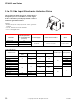
Connections CP-8391-456 mounts directly to the actuator.
Electronic Actuator Drive outputs
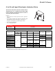
Electrical Refer to Typical Actuators Model Chart for triac output compatible actuators.
Environment
Ambient temperature limits
Shipping and storage: -40 to 140°F (-40 to 60°C).
Operating: -13 to 140°F (-25 to 60°C).
Humidity 5 to 95% RH, non-condensing.
Locations NEMA Type 1.
Dimensions
CP-8391-456 4-1/16 W x 4-5/8 H x 3-3/8 D in. (103 x 118 x 86 mm).
Agency Listing UL Recognized.
General Instructions Refer to F-24190.
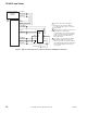
Actuator
1
1
1 Black/White (240 Vac) (Wire to L1 on
240 Vac actuators and tape Blue lead.)
CP-8391-456 power can be supplied
by source other than actuator.
2 CAUTION: Actuator must not have
built-in transformer; or if a built-in
transformer is present, remove red and
blue leads from the transformer to
terminals 7 and 8 and tape off.
3 All references to direction of actuator
shaft rotation are determined by
looking at the face of the actuator with
the output shaft.
4
3
2
X
– (Black)
+ (Red)
Orange
7
8
L1
L2 COM
Yellow
Brown
White/Blue
Black/Blue
Red/Yellow
Violet
CP-8391-456
From Vdc
Controller
2 3
Blue (120 Vac)
AC Supply