
Accessory List
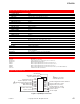
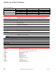
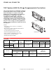

CP-8142-024
44
© Copyright 2006 TAC. All Rights Reserved. F-27382-1
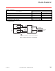
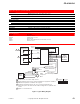
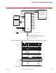
Figure 2 Connections to an Electric Vane Actuator.
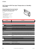
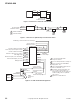
Figure 3 Connections to Hydraulically Controlled Vane Valves.
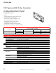
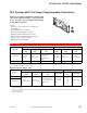
Figure 4 CP-8142-024 Terminal Designations.
120 Vac 60 Hz
Continuous Power
CP-8142 MP-485
Unload
Load
L1
L2
COM
3
2
X
1 CP-8142 Terminals.
2 24 Vac Secondary.
2
1
Load
Valve
Transformer
Hot(White) L2
120 Vac 60 Hz
Continuous Power
(Black) L1
COM
1
Load
Unload
Valve
1
Unload
+20
IO1
+6.2
ISA
AB1
ISB
IV1
RST
COM
Paralleling or Power Demand 10-0 Vdc Input
5 Vac Current
Transformer Input
0.5 Vac Current
Transformer Input
Current Transformer
Common
Chiller
Compressor
Motor
1 Do not interlock with Chiller
Compressor Motor.
2 For 2-15 Vdc Input Remove Jumper J1
.
3 Sensor Connections Chilled Water
Supply ISA – +6.2.
4 Option: Chilled Water Return Reverse
Reset of SPA ISB – +6.2.
5 Ground at Current Transformer only.
Use a common ground when one
transformer powers the CP-8142-024
and the loading valves for hydraulic
vane control.
6 Adjust for 0.5 Volts full load.
2
1
1
3
4
6
5
CP-8142-024
Chiller
Motor
Starter
Hot (Black)
Gnd (Blue/Black)
IV2
OP2
2 (Black)
3 (Black)
1 (White)
System Common
24 Vac 50/60 Hz
Continuous Power
Current Meter and
Paralleling
0-10 Vdc Output
Shunt
Resistance
Current
Transformer
+20 Vdc 35 mA Power Supply
Control Prop. Input-Output 2-15 Vdc
+6.2 Vdc 4 mA Power Supply
ISA Sensor Inputs (1000
W
Balco)
Aux. Bridge Input
S
B Sensor Inputs (1000 Ohm Balco)
Power Demand Input (15-2 Vdc)
Ramp-up Reset