
Accessory List
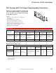
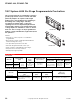

CP-8142-024
F-27382-1 © Copyright 2006 TAC. All Rights Reserved. 43
Accessories
Typical Applications
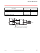
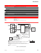
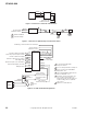
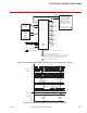
Figure 1 Typical Wiring Diagram.
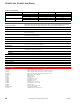
Specifications (Continued)
Environment
Ambient temperature limits
Shipping and storage: -40 to 160°F (-40 to 71°C).
Operating: 40 to 125°F (4 to 60°C).
Humidity 5 to 95% RH, non-condensing.
Locations NEMA Type 1.
Wiring connections
Control Coded screw terminals for 14 to 20 AWG.
Power Color coded pigtails, 10 in. (254 mm).
Cover Aluminum.
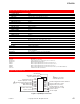
Mounting Unit is provided with a section of plastic track for panel mounting.
Dimensions 3-7/8 H x 11 W x 3-1/4 D in. (98 x 279 x 83 mm).
General Instructions Refer to F-17983.
Model No. Description
AD-8301 Minimum positioner.
ASP-584 Indicating meter 0 to 100%.
AT-215 Immersion well.
AT-8522 Remote setpoint adjuster, dual scale 30 to 80°F (1 to 26°C).
TS-8201 Immersion sensor.
1 TS-8000 Series 1000 Balco Temp. Sensor.
2 Supply and return water sensors must be installed in an appropriate well filled
with M-500 temperature conductive silicon grease.
3 Ground at Current Transformer only. Use a common ground when one
transformer powers the CP-8142-024 and the loading valves for hydraulic vane
control.
4 Adjust for 0.5 Volts full load.
5
5
1
1
2
CP-8142-024
Loading
Vane
Actuator
Electric or
Hydraulic
Chilled Water
Supply Sensor
Reset Sensor
COM
Unload
GND (Blue/Black)
Hot (Black)
Load
24 Vac
Power
+6.2
ISA
ISB
Terminal
2
3
Input Vac
0.5
5
5 Vac Current
Transformer Input
0.5 Vac Current
Transformer Input
Current Transformer
Common
Chiller
Compressor
Motor
4
3
Chiller
Motor
Starter
2 (Black)
3 (Black)
1 (White)
Shunt
Resistance
Current
Transformer