
Accessory List

CC-8104
28
© Copyright 2006 TAC. All Rights Reserved. F-27382-1
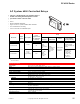
Accessories
Typical Applications
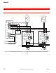
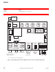
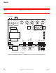
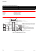
Figure 1 Typical Wiring Diagram for CC-8104.
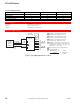
Maximum Electrical Rating per Output Stage 24 Vac
a
.
a
Minimum load amps: 0.1.
Amps VA Pilot Duty
0.9 (continuous) 22 (sealed)
9 (inrush) 220 (inrush)
Model No. Description
AD-8969-201 Offset resistor kit: 5, 10, 15 and 20°F.
AD-8969-301 1 K, ±1%, WW resistor kit.
AD-8969-901 Extended throttling range jumper.
AT-8100 Remote setpoint adjuster.
TOOL-201 Calibration kit for TAC System 8000.
TS-8000 1000 ohm Balco sensors.
ISA-Com
ISA
+6.2
AB1
AC Power Supply
B
W
IO1- R
To Maximum of
Two Controlled Devices
COM (Blue)
IV1 (Yellow)
135
W
Pot
TS-8000
Series
LO
LO
GRD
24 Vac
LO4
LO3
LO2
LO1
1K
W
AT-8122
AT-8155
AT-8158
Red
Blue
Yellow
Transformer
L2
L1
4
5
1
3
2
4
4
4
K4 K3 K2 K1
CC-8104
1 CC-8104 shipped as R A controllers Call for heat
(decreasing temp) energizes relays in sequence.
2 Remote setpoint is required if sensor other than
TS-8111.
3 24 Vac, 100 VA Max.
4 LO1 through LO4 terminals deliver 24 Vac
(22 VA max.) each as stages are energized.
External relays should be selected with VA
requirements not exceeding 24 Vac (22 VA
max.) each.
5 Internal solid state switching.