
Accessory List


VL500
310
© Copyright 2006 TAC. All Rights Reserved. F-27382-1
TAC Erie™ Zone Valve Control Center
Model Chart
Specifications
Accessories
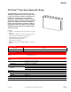
The VL500 zone control system provides control of
up to five zone valves, 7 VA or less per valve, a
circulator and boiler control in a multi-zone
hydronic heating system.
Field selectable priority for zone 1 eliminates the
need for additional relays to provide domestic hot
water priority. Additional zones can be added.
Features:
• Field selectable Priority Plus™ zone.
• Unlimited zone expansion. Maximum load on any serially
linked VL500 slave module should not exceed 58 VA.
• Field replaceable relays.
• LED status window.
• Common 24 Vac transformer terminal provides
compatibility with electronic thermostats.
• Field replaceable fuse.
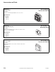
Model No. Description
VL500 Refer to Specifications.
Inputs
Power input 120 Vac @ 50/60 Hz, 90 VA.
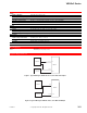
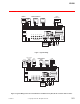
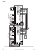
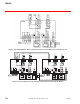
Connections See Figure 1 - Typical Wiring.
Outputs
Electrical
Thermostatic anticipator setting: 0.05 amps plus load current.
Transformer: 24 Vac, 75 VA (maximum load 58 VA).
Valve: 24 Vac, 0.9 A per output not to exceed 2.7 A total.
Boiler relay: Dry contacts.
Fuse ratings: F1 (24 Vac): 3.2 A, 125 V slow blow; F2 (120 Vac): 10 A, 250 V slow blow.
Circulator relay rating for 1/3 hp @ 120 V: Full load: 7.2 amps; Locked rotor: 43.2 amps.
Environment
Ambient temperature limits Operating: 32 to 104°F (0 to 40°C).
Humidity Up to 85% non-condensing.
Locations NEMA Type 1.
Dimensions 8 H x 12-3/8 W x 2-7/8 D inches (203 x 314 x 73 mm).
Agency Listing UL: Listed (file #E37601).
General Instructions Refer to F-27020.
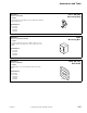
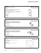
Model No. Description
40-8-47 F1 fuse (3.2 A / 250V Slo-Blo).
40-8-66 F2 fuse (10 A / 250V Slo-Blo).
VL500