
Accessory List
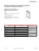


VER-HW Series
F-27382-1 © Copyright 2006 TAC. All Rights Reserved. 303
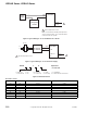
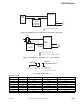
Figure 2 Typical Wiring for 4 to 20 mA External 12 to 24 Vdc Power Supply.
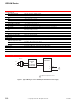
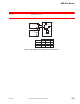
Figure 3 Typical Wiring for Three-Wire 0 to 5 or 0 to 10 Vdc Mode.
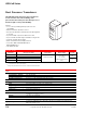
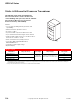
Figure 4 Model Information.
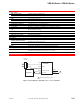
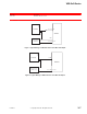
Resistance Curves.
°C °F
1K Platinum 10K Thermistor 10K Thermistor w/11K Shunt
-20 -04 921.60 78.910 9.654
-10 14 960.86 47.540 8.933
0 32 1000.00 29.490 8.044
10 50 1039.03 18.780 6.938
20 68 1077.94 12.260 5.798
25 77 1097.35 10.000 5.238
30 86 1116.73 8.184 4.696
40 104 1155.41 5.592 3.875
+
–
RH
Transmitter
1
1
Out
COM
1 Optional temperature sensor.
2
+
–
+
–
3
4
Controller
4-20 mA loop
750 ohm max
Power
Supply
12-24 Vdc
+
–
L1
L2
RH
Transmitter
Red
1
Out
COM
3 COM
1 Optional temperature sensor.
2 0-5 Vdc or 0-10 Vdc outboard selectable
24 Vdc
Controller
2 RH out
1 +
+
COM
RH
3
4
2
2 = 2% M = 4-20 mA 1 = 1K Platinum
3 = 3% V = 0-5V/0-10V 2 = 10K thermistor
3 = 10k thermisor w/11K shunt
VER-HW
Optional
Temperature Senso
r