
Accessory List
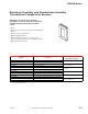


VER-HD Series, VER-HO Series
F-27382-1 © Copyright 2006 TAC. All Rights Reserved. 299
Specifications
Typical Applications
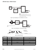
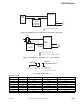
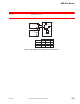
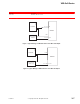
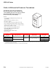
Figure 1 Typical Wiring for Three-Wire 0 to 5 or 0 to 10 Vdc Mode.
Sensing element
RH sensing element Thin-film capacitive, digitally profiled.
Temperature element 10K thermistor with 11K shunt or 1K platinum. 385 1000 ohms @0°C.
Accuracy
RH ± 2% or ± 3% at 10 to 90%.
Stability ± 1% at 68°F for two years.
Operating range 0 to 100% RH.
Temperature coefficient 0.1% RH below 25°C, -0.1% RH above 25°C.
Inputs
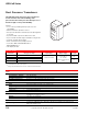
4 to 20 mA Two-wire 12 to 24 Vdc 30 mA. Minimum 750 ohm max loop resistance.
Vdc
0 to 5 or 0 to 10 Vdc, 12 to 24 Vdc or 24 Vac. 15 mA minimum. 24 Vac is a half wave device. Refer to
EN 206 (F-26363) for wiring.
Output
RH 4 to 20 mA Two-wire non-polarity sensitive.
RH 0 to 5 or 0 to 10 Vdc Three-wire observe polarity.
Temperature 10K with 11K shunt thermistor or 1K platinum or 10K thermistor.
Environment
Ambient temperature limits
Shipping and storage: -58 to 185°F (-50 to 85°C).
Operating: -58 to 122°F (-50 to 50°C).
Humidity 0 to 100% non-condensing.
Locations NEMA 4.
Housing Die-cast body, 304SS probe, PVC solar shield on outside models.
Mounting HD models are duct-mounted, HO models are outside mount.
Dimensions
HD: 4-19/32 H x 2-27/32 W x 2 D in. (117 x 72 x 51 mm).
HO: 4-19/32 H x 2-13/16 W x 2-5/16 D (117 x 71 x 52 mm).
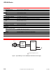
+
–
L1
L2
RH
Transmitter
Red
Black
1
Green
Orange
Orange
0-10 Vdc
1 Optional temperature sensor.
24 Vac or
24 Vdc
Controller
Analog Input
Blue
0-5 Vdc RH out
COM
–
+
or