
Accessory List


TSP-84x04, TSP-84x5x, TSP-85x03, & TSP-85x5x Series
F-27382-1 © Copyright 2006 TAC. All Rights Reserved. 297
Specifications
Accessories
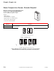
Typical Applications
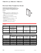
Construction
Self-contained temperature transmitter employing a platinum sensing element, 1000 Ω (±0.1%) at
32°F (0°C). Duct averaging models TSP-84704, TSP-84804, TSP-85703 and TSP-85803 employ
Balco sensing element, 1000 Ω ±1.0% at 70°F (21°C). All models are housed in a sturdy plastic
enclosure.
Output signal
Variable 4 to 20 mAdc for linear signal. High temperature = 20 mAdc,
mid-range temperature = 12 mAdc, and low temperature = 4 mAdc.
Span 16 mAdc (non-adjustable).
Current limit 30 mAdc.
Linearity 0.01% of span.
Hysteresis (deadband) 0%.
Short circuit duration Continuous.
Response time 400 microsec at full load.
Load resistance 25 through 900 Ω, dependent on power supply voltage. Refer to Figure 1.
Sensing element Duct averaging elements are ±1.8% of span.
Resistance change
Platinum: 2.14 Ω per F degree (3.85 Ω per C degree).
Balco sensor: 2.2 Ω per F degree (1.22 Ω per C degree) at 70°F (21°C).
Power requirements 12 Vdc (min.) to 30 Vdc (max.).
System performance
Element and transmitter Maximum error 0.8% of span.
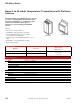
Environment
Ambient temperature limits
Shipping and storage: -40 to 140°F (-40 to 60°C).
Operating: electronic trans. assembly, 40 to 140°F (5 to 60°C); sensor, refer to Model Chart.
Humidity 5 to 95% RH, non-condensing.
Locations NEMA Type 1.
Connections Coded screw terminals.
Cover Beige plastic.
Dimensions 4-3/8 H x 2-7/8 W x 3-5/8 D in. (112 x 73 x 92 mm).
General Instructions Refer to F-24101.
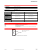
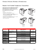
Model No. Description
AT-215 Stainless steel 6 in. bulb well insertion length, 7 in. overall length.
AT-226 Brass bulb well (required with immersion type sensors), 5.25 in. insertion length, 6.25 in. overall length.
AT-225 Stainless steel bulb well (required with immersion type sensors), 4 in. insertion length, 4-13/16 overall
length.
N2-4 Cover screw wrench.
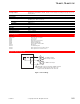
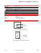
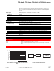
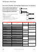
Figure 1 Maximum Load Resistance vs. Power Supply
Voltage.
Figure 2 Typical Wiring Diagram.
Power Supply Voltage, Vps
25
125
225
325
425
525
625
725
825
900
12 14 16 18 20 22 24 26 28
30
Maximum Load Resistance, RL
W
Operating Region
RL
W
(Max.) = (Vps - 11.6)/0.02
–
TSP 8x000
Transmitter
RL (Load Resistance)
at input to controller
or EMS system
–+
–
++Power Supply
(field provided)