
Accessory List


TSP-84xxx Series
F-27382-1 © Copyright 2006 TAC. All Rights Reserved. 295
Accessories
Typical Applications
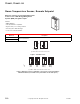
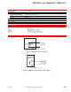
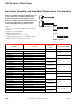
Figure 1 Typical System Wiring.
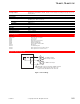
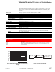
Figure 2 Maximum Load Resistance vs. Power Supply Voltage.
Specifications (Continued)
Environment
Ambient temperature limits
Shipping and storage: -40 to 140°F (-40 to 60°C).
Operating: 50 to 100°F (10 to 38°C).
Humidity 5 to 95% RH, non-condensing.
Locations NEMA Type 1.
Connections Coded screw terminals.
Cover Plastic, no thermometer.
Mounting Vertical, wall; TSP-84252 and TSP-85251 plenum rated.
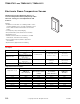
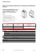
Dimensions
TSP-84152 4-3/8 H x 2-3/4 W x 1-5/8 D in. (111 x 70 x 43 mm).
TSP-84252 4-13/16 H x 3-1/4 W x 1-31/64 D in. (122 x 83 x 38 mm).
General Instructions Refer to F-24171.
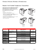
Model No. Description
ASP-83X1 Series Power supply.
AT-505 Surface mounting base TSP-84152 series only).
AT-1103 Wire guard.
AT-1104 Cast aluminum guard (TSP-84152 series only).
AT-1105 Plastic guard (TSP-84152 series only).
AT-8801 Non-flush 2 x 4 box adapter (TSP-84252 Series only).
N2-4 Cover screw wrench.
–+
–
++
–
TSP 84xxx/
Transmitter
RL (Load Resistance)
at Input to Controller
or EMS System
Power Supply
(field provided)
Power Supply Voltage, Vps
25
125
225
325
425
525
625
725
825
900
12 14 16 18 20 22 24 26 28
30
Maximum Load Resistance, RL
W
Operating Region
RL
W
(Max.) = (Vps - 11.6)/0.02