
Accessory List

TS-5191 Series
F-27382-1 © Copyright 2006 TAC. All Rights Reserved. 277
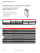
Adjustable Wall Sensor
Model Chart
Specifications
Accessories
Typical Applications
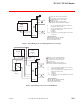
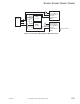
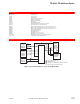
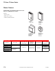
Figure 1 Installation Wiring Diagram of Optional TS-5191.
This sensor provides electronic sensing of room
temperature through a wall mounted device. It is
designed for use with the CP-5341 Fan Speed
Controller.
Features:
• Remote setpoint and control of CP-5341.
• Available with lock cover screw kits.
• Dial stop pins limit dial range.
Model No. Description
TS-5191 Refer to Specifications.
Sensing element Thermistor.
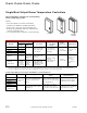
Control dial Marked “cooler/warmer” with approximate range of 55 to 85°F (13 to 29°C).
Ambient temperature limits
Shipping and storage: -40 to 160°F (-40 to 71°C).
Operating -40 to 135°F (-40 to 57°C).
Connections Coded screw terminals.
Cover Beige plastic.
Locations NEMA Type 1.
Mounting Wall.
Dimensions 4-3/8 H x 2-3/4 W x 1-5/8 D in. (111 x 70 x 43 mm).
General Instructions Refer to F-23768.
Model No. Description
AT-101 Lock cover kit.
AT-104 Dial stop pins.
AT-504 Plaster hole cover kit (small).
AT-505 Surface mounting base.
AT-546 Auxiliary mounting plate.
AT-602 Selector switch sub-base DP4T.
AT-603 Selector switch sub-base one DP4T, one DPDT.
AT-1103 Wire guard.
AT-1104 Cast aluminum guard.
AT-1155 Plastic guard, 6-1/4 H x 5-1/2 W x 3-1/4 D in.
AT-1165 Plastic guard, 8 H x 5-1/2 W x 3-1/2 D in.
-
5191
r
ies
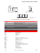
TS-5191
Remote
Sensing only
7
6
8
Remote Sensing
and
Remote Setpoint
TS-5191 Functions
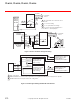
To CP-5341
Remote
Setpoint only